Sealing connection structure of retractable automobile
A technology of connecting structure and telescopic structure, which is applied to the connection between the body and the frame, the substructure, the vehicle parts, etc., to achieve the effect of improving the service life and strengthening the connection strength
- Summary
- Abstract
- Description
- Claims
- Application Information
AI Technical Summary
Problems solved by technology
Method used
Image
Examples
Embodiment 1
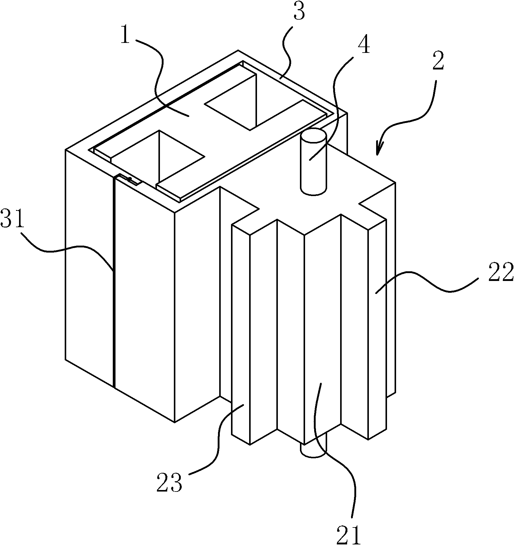
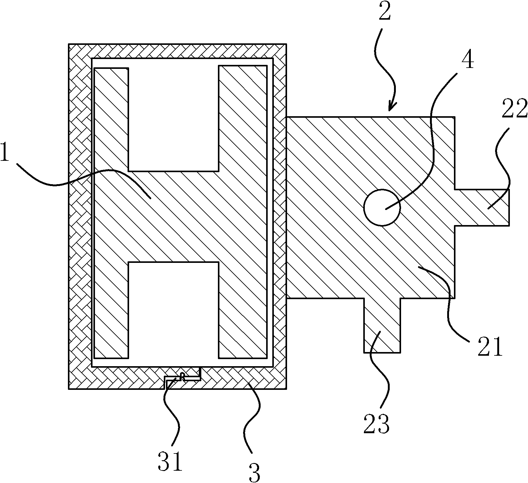
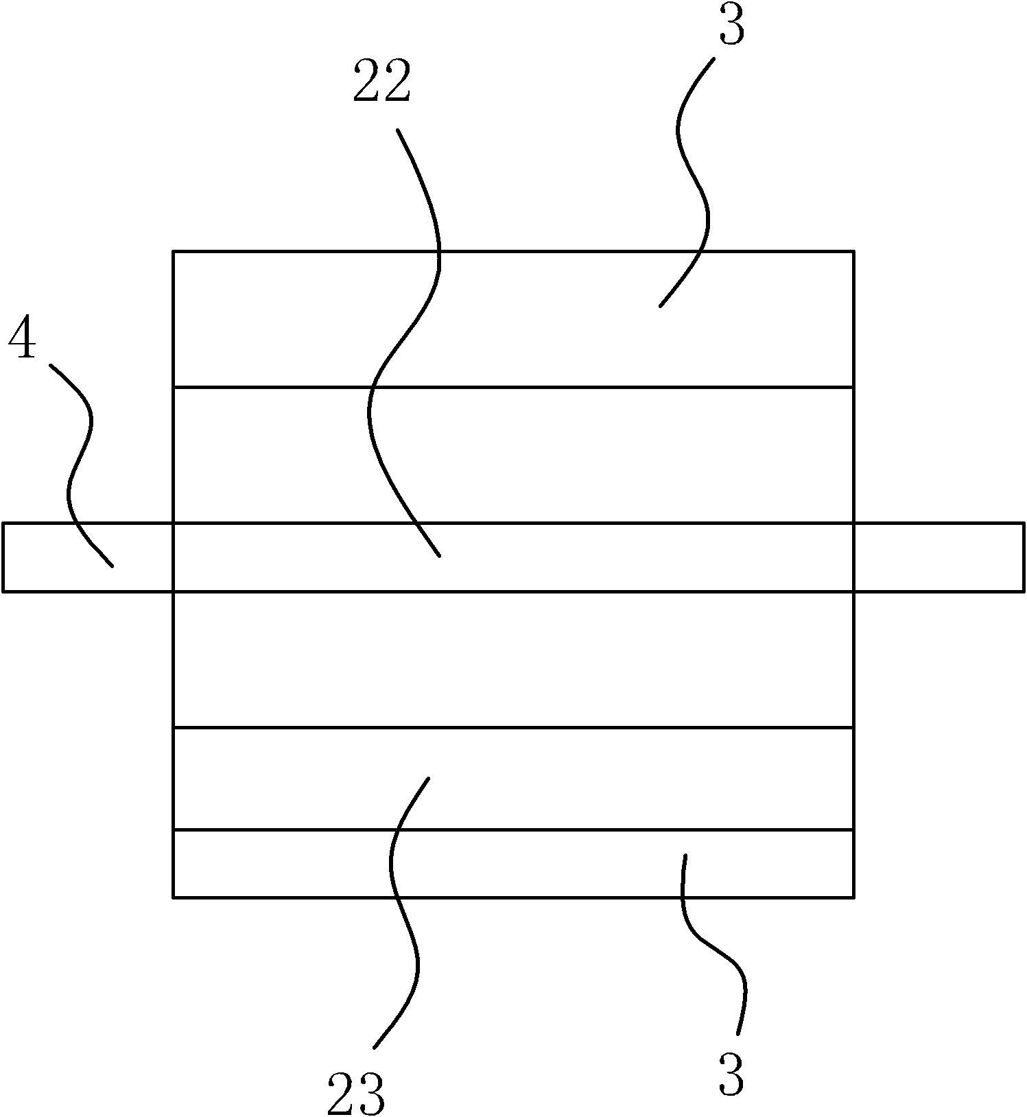
[0029] The chassis of the telescopic automobile has a movable beam 1 with a cross-section in the shape of an "I", and the expansion and contraction of the automobile is realized through the expansion and contraction of the movable beam 1. Such as figure 1 As shown, the sealed connection structure of the retractable automobile is located at the chassis and side walls of the automobile, and it includes a connecting arm 2 and a sealing sleeve 3. The connecting arm 2 is made of steel material, and the sealing sleeve 3 is made of rubber material. As a result, the sealing sleeve 3 is vulcanized on the connecting arm 2. Such as figure 1 As shown, the sealing sleeve 3 is sleeved around the movable beam 1 of the chassis to seal the movable beam 1 and prevent dust and sand from sticking to the movable beam 1 of the chassis.
[0030] The connecting arm 2 of this retractable automobile is fixed on the automobile by the limit shaft 4, as figure 1 , 2 As shown in and 3 , the limiting sh...
Embodiment 2
[0034] The structural principle of this embodiment is basically the same as that of Embodiment 1, the difference is that, as Figure 4 As shown, the front end surface of the body 21 is provided with a front limit shaft 51 for limiting the body 21, and the rear end surface of the body 21 is provided with a rear limit shaft 52 for limiting the body 21. The shaft 51 and the rear limiting shaft 52 are located on the same axis.
[0035] In order to facilitate the positioning of the front limit shaft 51 and the rear limit shaft 52, a front mounting hole is provided on the front end surface of the body 21, and a rear mounting hole is provided on the rear end surface of the body 21. The front limit shaft 51 is positioned on In the front mounting hole, the rear limiting shaft 52 is positioned in the rear mounting hole.
PUM
 Abstract
Description
Claims
Application Information
 - R&D
- Intellectual Property
- Life Sciences
- Materials
- Tech Scout
- Unparalleled Data Quality
- Higher Quality Content
- 60% Fewer Hallucinations
Browse by: Latest US Patents, China's latest patents, Technical Efficacy Thesaurus, Application Domain, Technology Topic, Popular Technical Reports.
© 2025 PatSnap. All rights reserved.Legal|Privacy policy|Modern Slavery Act Transparency Statement|Sitemap|About US| Contact US: help@patsnap.com


