Device for simulating load capacity of door lock during closing of sliding door of automobile

A technology of load force and door lock, which is applied in the field of simulation devices, can solve the problems of increasing the labor force of testers, cumbersomeness, and high site requirements, and achieve the effects of shortening the research and development cycle, simplifying test steps, and facilitating test work

Inactive Publication Date: 2013-06-05
NINGBO XINTAI MACHINERY
View PDF6 Cites 0 Cited by
  • Summary
  • Abstract
  • Description
  • Claims
  • Application Information

AI Technical Summary

Problems solved by technology

Existing durability tests on the sealing strip to close the door elastically pull the door lock are all done directly on the vehicle body, which causes many inconveniences:
[0004] 1. The price of the body during the test is relatively expensive, and the corresponding body of various door locks is not the same, so it is inconvenient to purchase and the cost is also high
[0005] 2. The car body itself has a relatively large space, and the door lock environment test and other requirements require simulation functions. This test requires a relatively large space and requires relatively high site requirements.
[0006] 3. The structure of the electric sliding door is relatively complicated, and the structures of various doors and door locks are different. It is cumbersome to assemble the entire door lock system on the door, and it is not convenient to disassemble and adjust the door lock, so the test cost is reduced. efficiency, greatly increasing the labor force of the testers
[0007] Therefore, the traditional electric sliding door durability test system is not only costly and complex to use, but also time-consuming, taking up a lot of labor and money

Method used


Image

  • Device for simulating load capacity of door lock during closing of sliding door of automobile
  • Device for simulating load capacity of door lock during closing of sliding door of automobile
  • Device for simulating load capacity of door lock during closing of sliding door of automobile

Examples


Embodiment Construction

[0020] The present invention will be further described in detail below in conjunction with the accompanying drawings and embodiments.

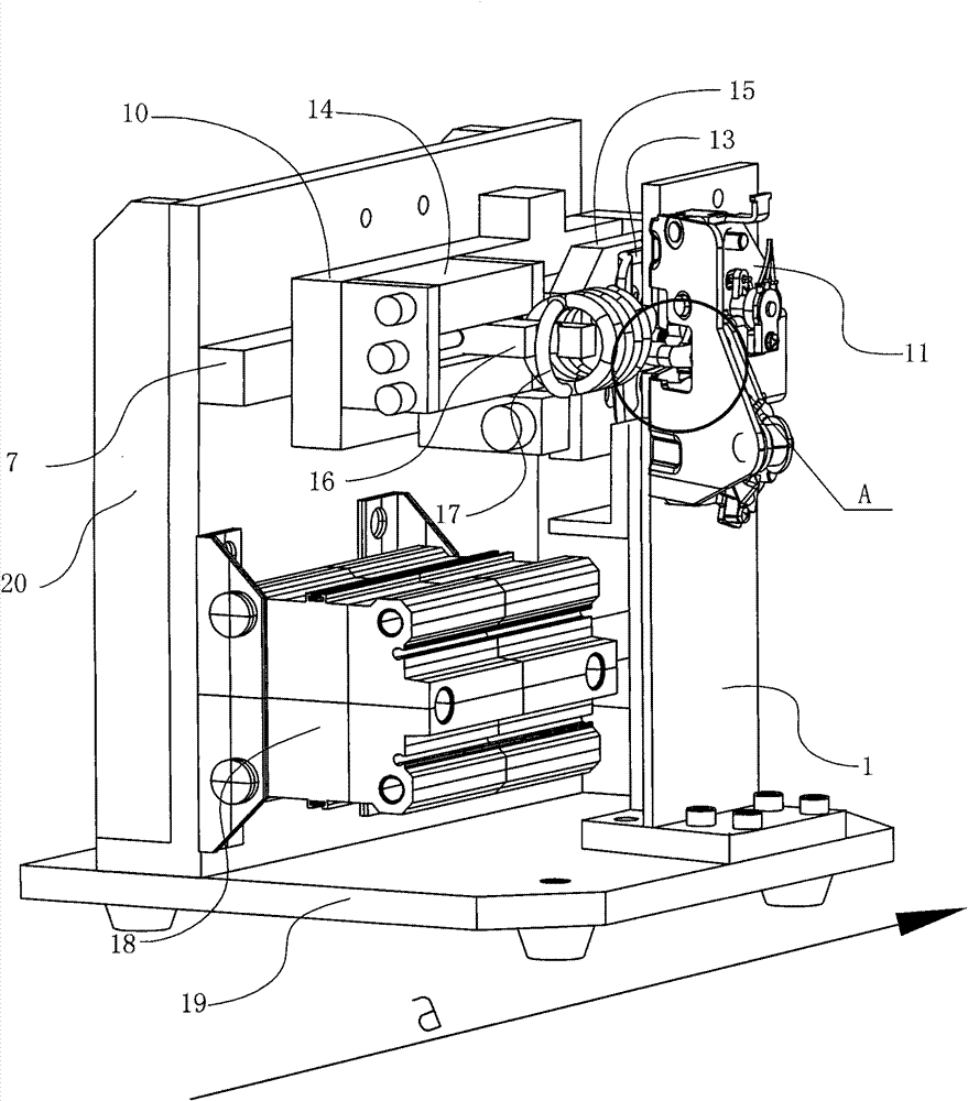
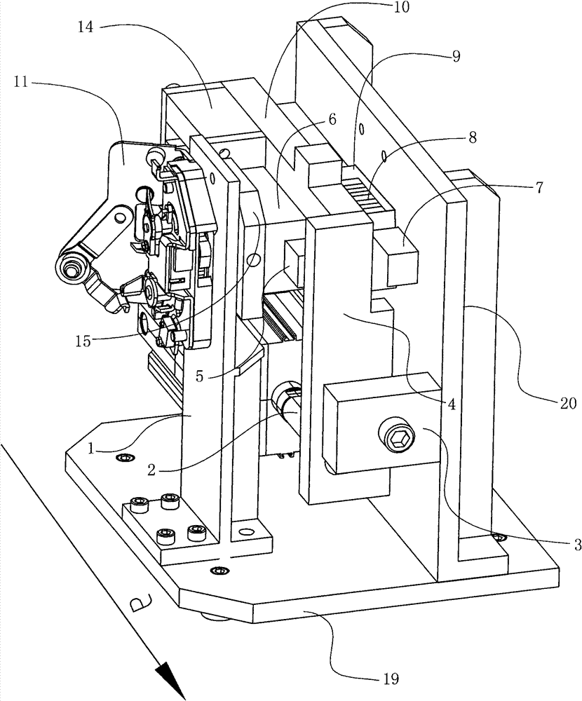
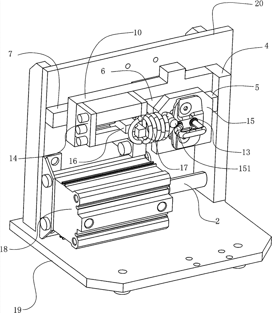
[0021] The device of the present invention for simulating the load force of the door lock when the sliding door of the automobile is closed, such as Figure 1-4 As shown, it includes a base plate 19, a door lock mounting plate 1 and a fixed mounting plate 20 vertically fixed on the base plate 19, and the door lock mounting plate 1 and the fixed mounting plate 20 are arranged in parallel at a certain distance. A transverse linear guide rail 7 is fixed on the fixed mounting plate 20 , the load mounting plate 10 is mounted on the linear guide rail 7 , and the load mounting plate 10 can move laterally on the linear guide rail 7 along the linear guide rail 7 .

[0022] One end of the load mounting plate 10 is also fixed with a vertical load transition plate 4 perpendicular to the load mounting plate 10, and the other end of the load mounting plate ...


PUM


Abstract

The invention relates to a device for simulating load capacity of a door lock during the closing of a sliding door of an automobile. The invention is characterized in that the device comprises a base plate, fixed installing plates and a door lock installing plate, wherein the fixed installing plates are vertically arranged on the base plate at intervals and are provided with a transverse linear guide rail and a power source which drives a load installing plate to move along the linear guide rail; a transverse guide rail is fixed on the load installing plate; a sliding block is arranged on theguide rail; a load spring is connected between the load installing plate and the sliding block; a lock column installing plate is also fixed at the outer side of the sliding block; a lock column is arranged on the lock column installing plate; and the door lock corresponding to the lock column is arranged on the door lock installing plate. With the adoption of the simulating device, as the durability test of the door lock can be transferred from an automobile body to a laboratory table, the cost is saved, the test steps are simplified, and the period of product development is shortened.

Description

technical field [0001] The invention relates to a simulation device, in particular to a device for simulating the load force of a door lock when a sliding door of an automobile is closed. Background technique [0002] With the rapid development of the domestic automobile industry, the share of MPVs in the domestic market is increasing year by year, and MPVs are generally equipped with single or double sliding doors. In addition, electric sliding doors are becoming more and more popular. [0003] The existing electric sliding door structure has a sealing strip on the door, and when the electric sliding door is closing the door, when the sealing strip touches the vehicle body, the sealing strip will be subjected to a reverse elastic force, and the lock cylinder will generate a pulling force on the door lock ratchet. Existing durability tests on the sealing strip to close the door elastically pull the door lock are all done directly on the vehicle body, which causes many inconv...

Claims


Application Information

Patent Timeline
Patent Type & Authority Patents(China)
IPC IPC(8): G01M13/00
Inventor 徐竞超
Owner NINGBO XINTAI MACHINERY
Why Eureka
Try Eureka