Pressure stabilizing valve for crankcase for engine

A crankcase and engine technology, applied in engine components, crankcase ventilation, machine/engine, etc., can solve the problems of slow response of crankcase pressure, high relative pressure of crankcase, oil channeling, etc., to ensure service life and reduce channeling. The effect of oil quantity and convenient operation

Inactive Publication Date: 2016-12-07
GUANGXI YUCHAI MASCH CO LTD
View PDF10 Cites 0 Cited by
  • Summary
  • Abstract
  • Description
  • Claims
  • Application Information

AI Technical Summary

Problems solved by technology

[0002] At present, in the local simulation test of the engine on the plateau, the air pressure at both ends of the engine inlet and exhaust is mainly simulated to realize the simulation of the plateau environment. If the open crankcase system is not changed to a closed one (that is, forced ventilation, the outlet of the oil-gas separator and the engine air inlet connection), it will cause the relative pressure of the crankcase to be too large, which will affect the authenticity of the test, and the internal resistance of the engine and the pressure of the seal will be too large, which is prone to various risks; Because the engine itself is designed as an open crankcase, changing it to a closed one will inevitably lead to the problem of excessive oil leakage in the crankcase caused by unstable air pressure. In addition, the air pressure at one end of the intake pipe simulated on the plateau may be reduced. Because of the sudden increase and decrease of the air pressure due to its control problems, the crankcase pressure response is slow, and the instantaneous pressure difference will reduce the working efficiency of the engine oil-gas separation system, and may even produce a large amount of blow-by oil. A large amount of oil enters the supercharger, intermediate Cooler, affecting the service life of the engine itself and related accessories

Method used


Image

  • Pressure stabilizing valve for crankcase for engine

Examples


Embodiment Construction

[0013] Below in conjunction with embodiment, the present invention is further described, but does not constitute any restriction to the present invention, anyone makes the limited number of amendments in the scope of claims of the present invention, still within the scope of claims of the present invention.

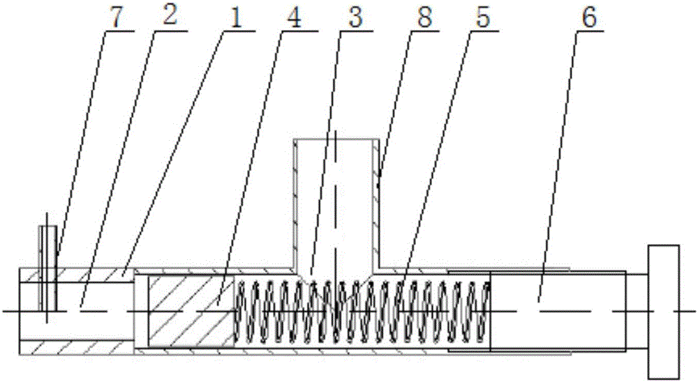
[0014] The specific embodiment of the present invention is like this: with reference to figure 1 Shown, a kind of engine crankcase pressure-stabilizing valve comprises hollow columnar valve body 1, and one end of valve body 1 is provided with the intake cavity 2 that connects engine crankcase outlet, and the other end is closed, and the side wall of valve body 1 is provided with There is an air outlet 3 connected to the oil-gas separator, and the cavity of the valve body 1 between the air inlet chamber 2 and the closed end is an adjustment chamber, and the adjustment chamber is equipped with a controllable conduction or cut-off regulator. The air pressure in the intake c...


PUM


Abstract

The invention discloses a pressure stabilizing valve for a crankcase for an engine. The valve comprises a hollow cylindrical valve body; an air inlet cavity connected with an outlet of the crankcase for the engine is arranged at one end of the valve body; the other end of the valve body is sealed; an air outlet connected with an oil-gas separator is arranged on the side wall of the valve body; a valve body cavity between the air inlet cavity and the sealed end is an adjusting cavity; and a pressure stabilizing device capable of controlling connection or disconnection of the air inlet cavity and the air outlet is arranged in the adjusting cavity. The valve is reasonable in structure and ensures that pressure of the crankcase for the engine is in a certain optimal and stable range which meets working requirements of an oil-gas separation system, the oil pumping amount of the crankcase for the engine is greatly reduced, and the service life of the engine and the service life of related accessories are guaranteed.

Description

technical field [0001] The invention relates to the field of engines, more specifically, it relates to an engine crankcase pressure stabilizing valve. Background technique [0002] At present, in the local simulation test of the engine on the plateau, the air pressure at both ends of the engine inlet and exhaust is mainly simulated to realize the simulation of the plateau environment. If the open crankcase system is not changed to a closed one (that is, forced ventilation, the outlet of the oil-gas separator and the engine air inlet connection), it will cause the relative pressure of the crankcase to be too large, which will affect the authenticity of the test, and the internal resistance of the engine and the pressure of the seal will be too large, which is prone to various risks; Because the engine itself is designed as an open crankcase, changing it to a closed one will inevitably lead to the problem of excessive oil leakage in the crankcase caused by unstable air pressur...

Claims


Application Information

Patent Timeline
Patent Type & Authority Applications(China)
IPC IPC(8): F01M13/00F01M13/04
CPCF01M13/00F01M13/04F01M2013/0005
Inventor 陆景东徐国龙曹斌肖文龙雷铜刘泳梁雄超祁智慧
Owner GUANGXI YUCHAI MASCH CO LTD
Why Eureka
Try Eureka