Method for transmission in a wireless communication system

A technology for wireless communication systems and transmission antennas, applied in wireless communication, transmission systems, digital transmission systems, etc., can solve the problems of not being able to improve space efficiency, and that a single antenna user terminal cannot receive multiple layers, so as to avoid signal cancellation and high The effect of space efficiency

Active Publication Date: 2013-08-07
HUAWEI TECH CO LTD
View PDF2 Cites 0 Cited by
  • Summary
  • Abstract
  • Description
  • Claims
  • Application Information

AI Technical Summary

Problems solved by technology

Therefore, in these types of systems, the use of SMUX schemes does not improve space efficiency, because single-antenna user terminals cannot receive multi-layer

Method used


Image

  • Method for transmission in a wireless communication system
  • Method for transmission in a wireless communication system
  • Method for transmission in a wireless communication system

Examples


Embodiment Construction

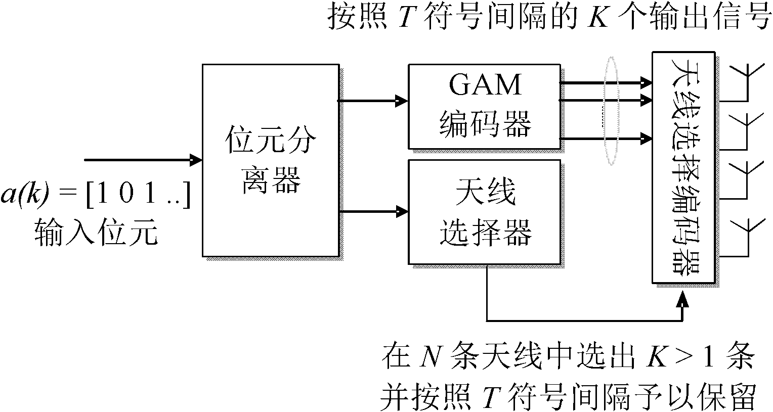
[0023] According to the aforementioned spatial modulation (SM) scheme, one of the N available transmission antennas is selected for transmission, that is to say

[0024] Bit

[0025] It can be encoded according to antenna selection and using a modulation constellation with M signal points, and then log 2 M bits can be coded according to the choice of modulation constellation symbols. In the above expression, It means that the value x should be as close as possible to the nearest integer value, because a small part of the bits cannot be transmitted through the selected antenna (it is very practical if two of the multiple transmission antennas are selected). therefore,

[0026] Bit

[0027] The total number can be transmitted to each channel used.

[0028] According to the GSSK scheme mentioned above, K antennas are selected for the information bits to be transmitted, and the remaining N-K antennas do not transmit anything. Through this method, select K among N antennas (K> 1) There...


PUM


Abstract

The present invention relates to a method for tr ansmission in a wireless communication system and more particularly to a method in a tran smitter which comprises a plurality of transmit antennas. An example embodiment according to th e invention comprises encoding of signals for transmission and provides for transmission ove r a selected number of transmit antennas.

Description

Technical field [0001] The present invention relates to transmission in a wireless communication system, and more specifically, to a method of transmission in a transmitter with multiple transmission antennas. In addition, a set of transmitter equipment related to this method will be disclosed. Background technique [0002] If a transmitter has multiple transmission antennas, it can be selected among various transmission schemes according to the transmission purpose. Transmission schemes can be divided into two categories according to heuristics, that is, in terms of their diversity and capacity. However, some transmission schemes have both capacity and diversity characteristics. [0003] In order to improve the reliability of the wireless link, the transmission diversity scheme has always been the mainstream in the prior art. Most transmission diversity schemes are usually designed on the basis of maintaining a simple receiver structure, and these schemes generally function nor...

Claims


Application Information

Patent Timeline
Patent Type & Authority Patents(China)
IPC IPC(8): H04B1/02
CPCH04L1/0643H04L1/0606H04W88/02
Inventor 马蒂尔斯·温斯特姆布兰尼斯拉夫·波波维奇雅普·范德比克
Owner HUAWEI TECH CO LTD
Why Eureka
Try Eureka