Bridge crane trolley for mine

A technology of bridge crane and trolley, which is applied in the direction of load trolley, traveling mechanism, load hanging element, etc., can solve the problems of equipment hoisting, maintenance and replacement difficulties, etc., and achieve the effect of solving hoisting difficulties

Inactive Publication Date: 2013-09-04
HENAN MINE CRANE
View PDF0 Cites 0 Cited by
  • Summary
  • Abstract
  • Description
  • Claims
  • Application Information

AI Technical Summary

Problems solved by technology

[0005] The object of the present invention is to provide a bridge crane trolley for mines, so as to solve the technical problem in the prior art that it is difficult to lift out the equipment in the mine for maintenance and replacement

Method used


Image

  • Bridge crane trolley for mine
  • Bridge crane trolley for mine
  • Bridge crane trolley for mine

Examples


Embodiment Construction

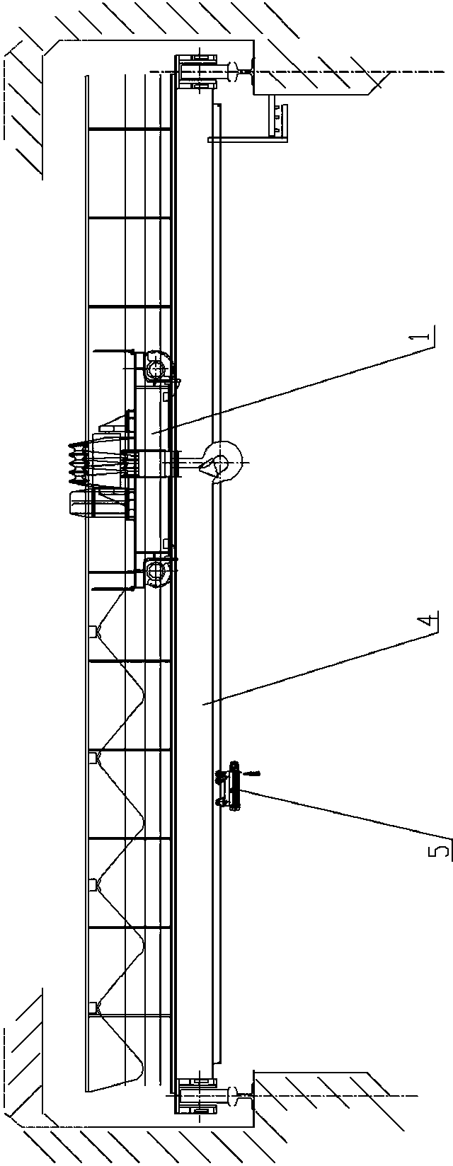
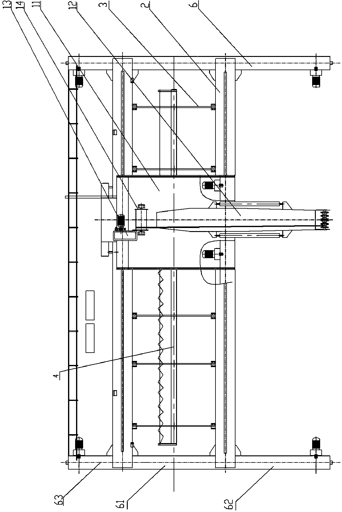
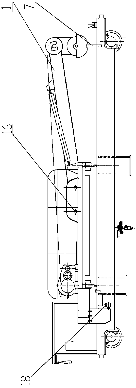
[0019] Such as Figure 1 to Figure 5 As shown, a bridge crane for mines includes two main beams 2 horizontally arranged, and two end beams 6 are fixedly connected to the ends of the two main beams 2. The main beam 2 and the end beam 6 constitute a crane bridge frame. The end beam 6 is provided with a trolley traveling mechanism, which includes wheels arranged at both ends of the end beam and a traveling motor for driving the wheels to rotate, and a guide rail extending in the extension direction of the main beam is fixed on the main beam 2 A crane trolley 1 is provided on the guide rail. The crane trolley 1 includes a trolley chassis 11 slidably mounted on the guide rail. A reel 14 is provided on the trolley chassis 11, and the reel 14 is driven by a motor 13 to roll on the trolley chassis 11. One side of the tube 14 is fixedly provided with a cantilever beam 12 outside the chassis of the trolley extending upward, and the cantilever beam 12 is arranged obliquely to the plane of...


PUM


Abstract

The invention discloses a bridge crane trolley for a mine, which comprises a trolley chassis, wherein a hoisting mechanism is arranged on the trolley chassis; the hoisting mechanism comprises a winding drum which is rotatably installed on the trolley chassis; the hoisting mechanism also comprises a cantilever beam which is fixedly arranged at one side of the winding drum on the trolley chassis and extends out of the trolley chassis; one end of the cantilever beam, far away from the trolley chassis, is provided with a fixed pulley block; a traction rope is wound on the fixed pulley block; and one end of the traction rope is connected to the winding drum, and the other end is fixedly connected with a hoisting appliance. The end part of the cantilever beam, provided with the fixed pulley block, is positioned outside a main beam, therefore, barriers can be effectively kept away when objects in the mine are hoisted, the space is saved and the problem of difficulty in hoisting equipment in the mine is effectively solved.

Description

Technical field [0001] The invention belongs to the technical field of hoisting machinery, and in particular relates to an overhead crane trolley for mines. Background technique [0002] Cranes are commonly used material handling equipment and are widely used in factories, docks, freight yards and other places. At present, in the process of installation, maintenance and replacement of underground equipment in coal mines, the transmission method mostly uses simple lifting tools such as poles or chain hoists. Workers have high labor intensity and low efficiency, and it is often necessary to remove buildings and equipment around the mine head. It caused great losses in financial resources, manpower and time, and affected the production efficiency of coal mines. [0003] Most of the existing bridge cranes include two main beams and two end beams fixed at both ends of the main beam in parallel. The end beams are provided with a cart traveling mechanism for driving the main beam and the...

Claims


Application Information

Patent Timeline
Patent Type & Authority Patents(China)
IPC IPC(8): B66C11/00B66C9/08
Inventor 高明利任海涛
Owner HENAN MINE CRANE
Why Eureka
Try Eureka