Synchronous rectification control circuit and control method thereof

A technology of synchronous rectification and synchronous control, which is applied in the direction of control/regulation system, electrical components, and adjustment of electrical variables, etc., which can solve the problems of reduced control efficiency, easy distortion of small signals, and influence of MOSFET accuracy, and achieve the goal of eliminating parasitic parameters effect, improve control efficiency, and avoid distortion

Active Publication Date: 2013-10-09
HUAWEI DIGITAL POWER TECH CO LTD
View PDF4 Cites 0 Cited by
  • Summary
  • Abstract
  • Description
  • Claims
  • Application Information

AI Technical Summary

Problems solved by technology

[0004] However, the inventor found the following problems in the prior art during the process of implementing the present invention: the synchronous rectification control in the prior art is realized by sampling the voltage across the MOSFET, and the MOSFET itself has many parasitic components such as equivalent inductance and junction capacitance. Parameters, which affect the accuracy of the MOSFET's turn-on or turn-off control, it is difficult to ensure that the circuit works in the best state; and sampling a small signal through a large signal is prone to distortion, which reduces the control efficiency

Method used


Image

  • Synchronous rectification control circuit and control method thereof
  • Synchronous rectification control circuit and control method thereof
  • Synchronous rectification control circuit and control method thereof

Examples


Embodiment Construction

[0027] In order to make the purpose, technical solutions and advantages of the embodiments of the present invention clearer, the technical solutions in the embodiments of the present invention will be clearly and completely described below in conjunction with the drawings in the embodiments of the present invention. Obviously, the described embodiments It is a part of embodiments of the present invention, but not all embodiments. Based on the embodiments of the present invention, all other embodiments obtained by persons of ordinary skill in the art without creative efforts fall within the protection scope of the present invention.

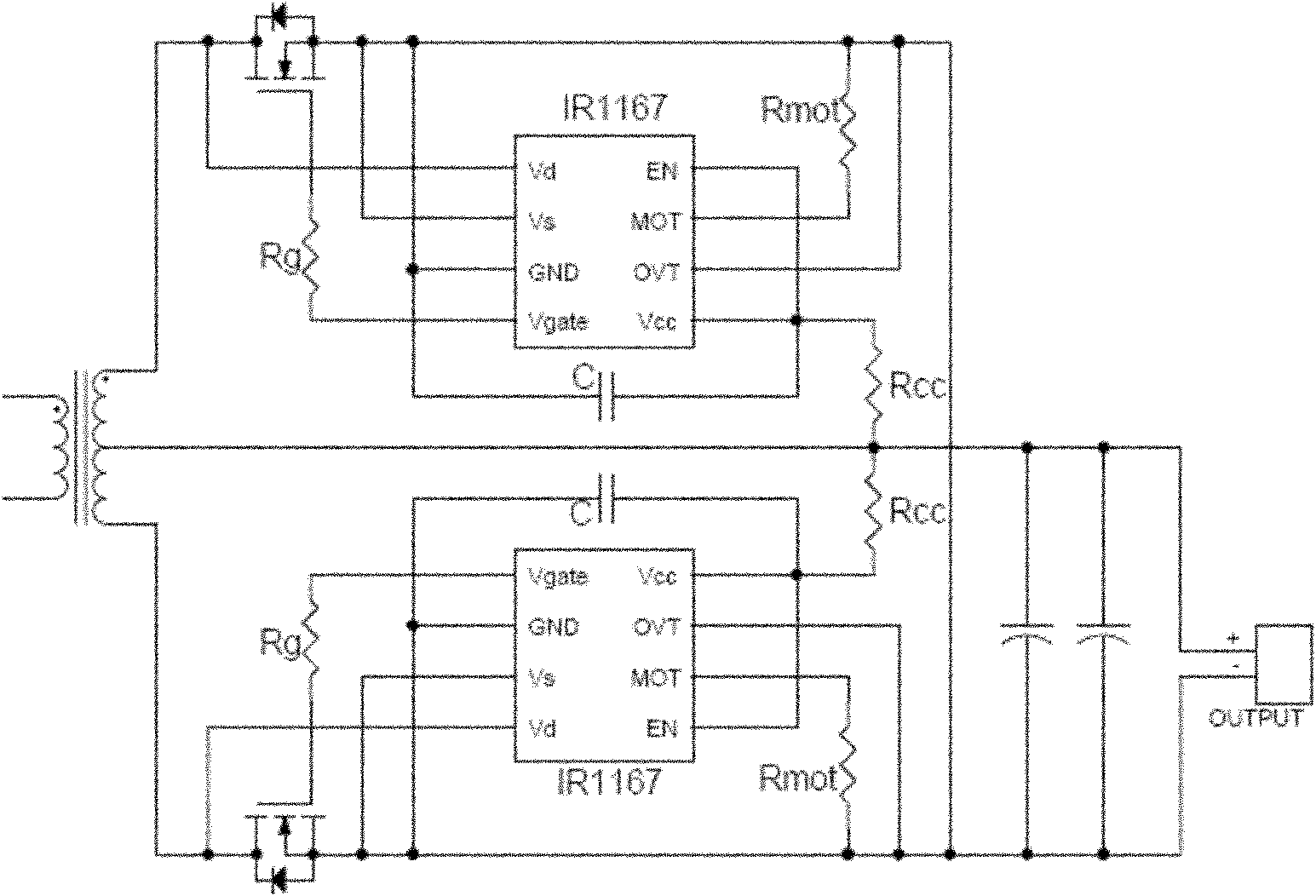
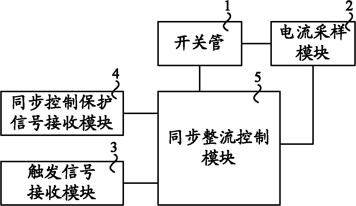
[0028] image 3 It is a schematic structural diagram of Embodiment 1 of the synchronous rectification control circuit of the present invention, as shown in image 3 As shown, this embodiment provides a synchronous rectification control circuit, which may specifically include at least one switch tube 1, a current sampling module 2, a trigger signa...


PUM


Abstract

The embodiment of the invention discloses a synchronous rectification control circuit and a control method thereof, and the circuit comprises at least one switching tube, a current sampling module, a trigger signal receiving module, a synchronization control protection signal receiving module and a synchronous rectification control module, wherein the synchronous rectification control module is used for performing forced conduction on the switching tube which is currently controlled by a synchronization control protection signal provided by the synchronization control protection signal receiving module under triggering of a trigger signal provided by the trigger signal receiving module, detecting voltage or current acquired by the current sampling module, and turning off the switching tube which is currently controlled by the synchronization control protection signal. The invention further provides the synchronous rectification control method. By adopting the control circuit and the control method, impacts caused by a parasitic parameter in a switch are eliminated, the distortion generated by sampling a small signal on a big signal is avoided, and the control efficiency is improved.

Description

technical field [0001] Embodiments of the present invention relate to switching power supply technology, in particular to a synchronous rectification control circuit and a control method thereof. Background technique [0002] Synchronous rectification technology is currently a very common technology used in the field of switching power supplies. It uses a dedicated power metal oxide semiconductor field effect transistor (Metal Oxide Semiconductor Field Effect Transistor; hereinafter referred to as: MOSFET) with extremely low on-state resistance to replace the rectifier diode. To reduce rectification loss. At present, the traditional pulse width modulation (Pulse Width Modulation; hereinafter referred to as: PWM) control type synchronous rectification control is relatively simple, usually using the primary side drive voltage to perform synchronous rectification control, and if the phase of the secondary side current is inconsistent with the primary side voltage, This makes t...

Claims


Application Information

Patent Timeline
Patent Type & Authority Patents(China)
IPC IPC(8): H02M3/137
Inventor 徐金柱
Owner HUAWEI DIGITAL POWER TECH CO LTD
Why Eureka
Try Eureka