Circulation control device and method of induction electric power transmission system

A technology of inductive power transmission and circulating current control, applied in circuit devices, electromagnetic wave systems, electrical components, etc., can solve problems such as poor control effect, difficult realization, and distortion of resonance variable waveforms.

Active Publication Date: 2011-08-17
重庆前卫无线电能传输研究院有限公司
View PDF1 Cites 17 Cited by
  • Summary
  • Abstract
  • Description
  • Claims
  • Application Information

AI Technical Summary

Problems solved by technology

The researchers propose a way to use blocking diodes, which can block the circulating flow, but cause excessive blocking of energy in the resonant network, resulting in distortion of the resonance variable waveform
The researchers also proposed a phase compensation scheme for real-time detection of resonant frequency and circulating current duration by means of DSP chips. Realization, and the complex control method in the realization process also makes the control delay larger, resulting in poor control effect

Method used


Image

  • Circulation control device and method of induction electric power transmission system
  • Circulation control device and method of induction electric power transmission system
  • Circulation control device and method of induction electric power transmission system

Examples


Embodiment Construction

[0050] All features disclosed in this specification, or steps in all methods or processes disclosed, may be combined in any manner, except for mutually exclusive features and / or steps.

[0051] Any feature disclosed in this specification (including any appended claims, abstract and drawings), unless expressly stated otherwise, may be replaced by alternative features which are equivalent or serve a similar purpose. That is, unless expressly stated otherwise, each feature is one example only of a series of equivalent or similar features.

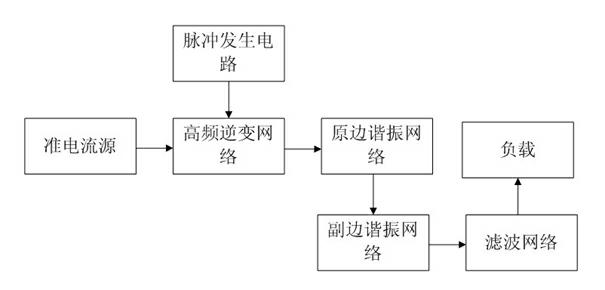
[0052] like figure 1 As shown, the parallel inductive power transfer system can be divided into the primary part (energy transmitting end) and the secondary part (energy receiving end). In the primary part, the quasi-current source is connected to the high-frequency inverter network, and outputs DC power to the high-frequency inverter network; the pulse generation circuit is connected to the high-frequency inverter network, and the output con...


PUM


Abstract

The invention discloses a circulation control device and a method of an induction electric power transmission system, which belong to the field of induction electric power transmission control. The circulation control method provides a method for obtaining frequency difference and frequency compensation direction between a forced oscillation frequency and an inherent resonance frequency accordingto a circulation duration time and a voltage peak value, wherein the method comprises the following steps of: obtaining the circulation duration time through a first current transformer and a first comparator; then obtaining a circulation peak value by means of FPGA (Field Programmable Gate Array); obtaining the frequency difference compensation direction through a second current transformer and a second comparator; judging whether the bidirectional circulation is mutated trough a differentiating circuit and a third comparator by means of FPGA, wherein when the bidirectional circulation is mutated, an AD (Average Deviation) collector is controlled to collect the voltage peak value which is corresponding to the bidirectional circulation by means of FPGA; and then recording the times for reaching to the circulation peak value in two close times by the FPGA, and obtaining the frequency difference by calculating according to the circulation peak value and the voltage peak value. The circulation control device and method of an induction electric power transmission system provided by the invention have the advantages that the purpose for accurately controlling the circulation in an induction electric power transmission system is achieved by the using of a circulation control device with low hardware requirement and a sample circulation control method.

Description

technical field [0001] The invention relates to a circulation control device and method, in particular to a circulation control device and method for an inductive power transmission system. Background technique [0002] In an inductive power transfer system, in order to generate a high-frequency energy transmission magnetic field, it is usually necessary to generate sinusoidal oscillations in the resonant network at the energy transmitting end, and the oscillation modes are usually divided into two types: autonomous oscillation and forced oscillation. [0003] The autonomous oscillation mode completes the switching of the high-frequency inverter network by utilizing the zero-crossing point of the system resonance variable. Therefore, the autonomous oscillation mode is a passive mode of operation, and the system oscillation frequency is determined by the parameters of the resonant network. However, this mode has the risk of resonance failure when the quality factor of the re...

Claims


Application Information

Patent Timeline
Patent Type & Authority Applications(China)
IPC IPC(8): H02J17/00H02J50/12
Inventor 戴欣王智慧苏玉刚唐春森孙跃
Owner 重庆前卫无线电能传输研究院有限公司
Why Eureka
Try Eureka