Filter

A technology for filters and filter areas, applied in the direction of fixed filter element filters, filtration separation, chemical instruments and methods, etc., can solve the problems of affecting the filtering effect, clogging the filter element, and poor sewage discharge effect, so as to achieve good sewage discharge effect and improve The effect of the filter effect

Inactive Publication Date: 2011-08-24
杨淼
View PDF6 Cites 5 Cited by
  • Summary
  • Abstract
  • Description
  • Claims
  • Application Information

AI Technical Summary

Problems solved by technology

This kind of filter has the following problems: 1. The liquid to be filtered that enters the filter area through the liquid inlet will impact the filter element vertically, and the granular dirt in the liquid to be filtered is easy to directly attach to the surface of the filter element,

Method used


Image

  • Filter
  • Filter
  • Filter

Examples


Example Embodiment

[0019] Example one

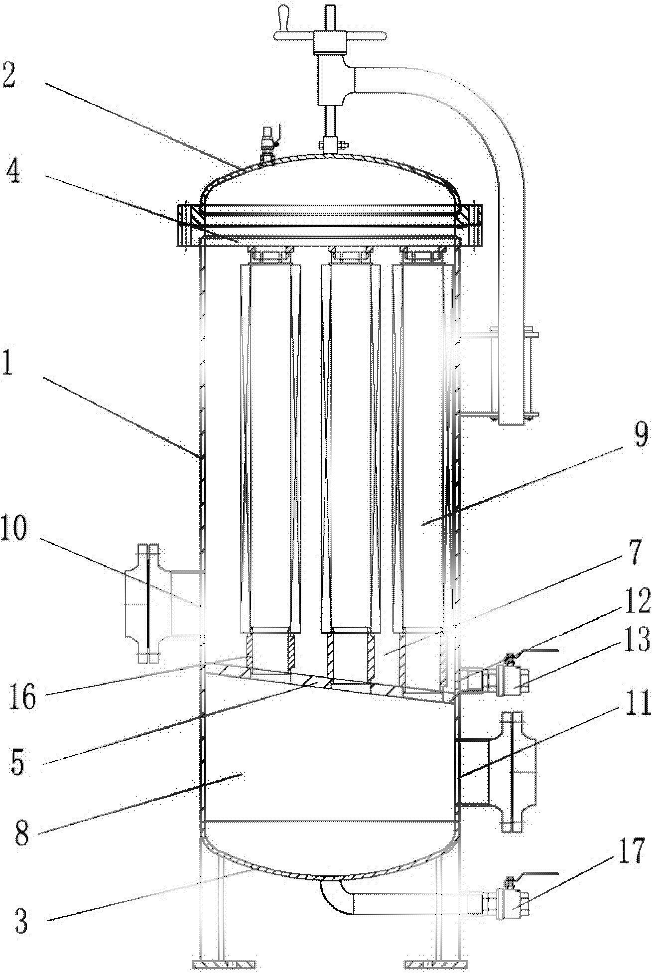
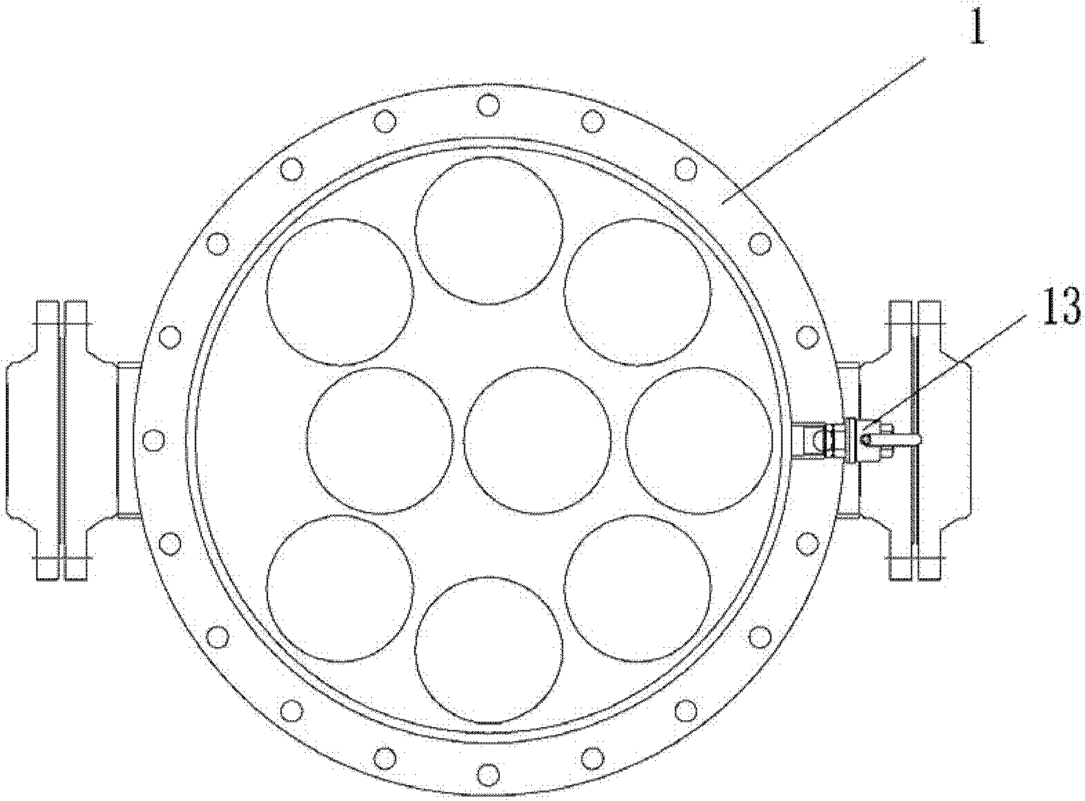
[0020] Such as figure 1 , figure 2 As shown, the filter of the present invention includes: a cylindrical body 1, an upper head 2, a lower head 3, a pressure plate 4, a filter element 9, a filter element seat 16 and a tube plate 5, a cylinder body 1, an upper head 2 and a lower head The head 3 forms a can-shaped body with a cavity in the center. The pressure plate 4 is connected to the inner wall of the top end of the cylindrical body 1. The tube plate 5 is inclined and fixedly connected to the inner wall of the cylindrical body 1. The tube plate 5 connects the cavity of the can-shaped body. It is divided into a filter area 7 and a clean liquid area 8. The upper end of the filter element 9 is connected to the pressure plate 4, the lower end of the filter element 9 is connected to the tube plate 5 through the filter element seat 16, and the side wall of the cylinder 1 is provided with a liquid inlet 10, The liquid outlet 11 and the sewage outlet 12, the liquid...

Example Embodiment

[0021] Example two

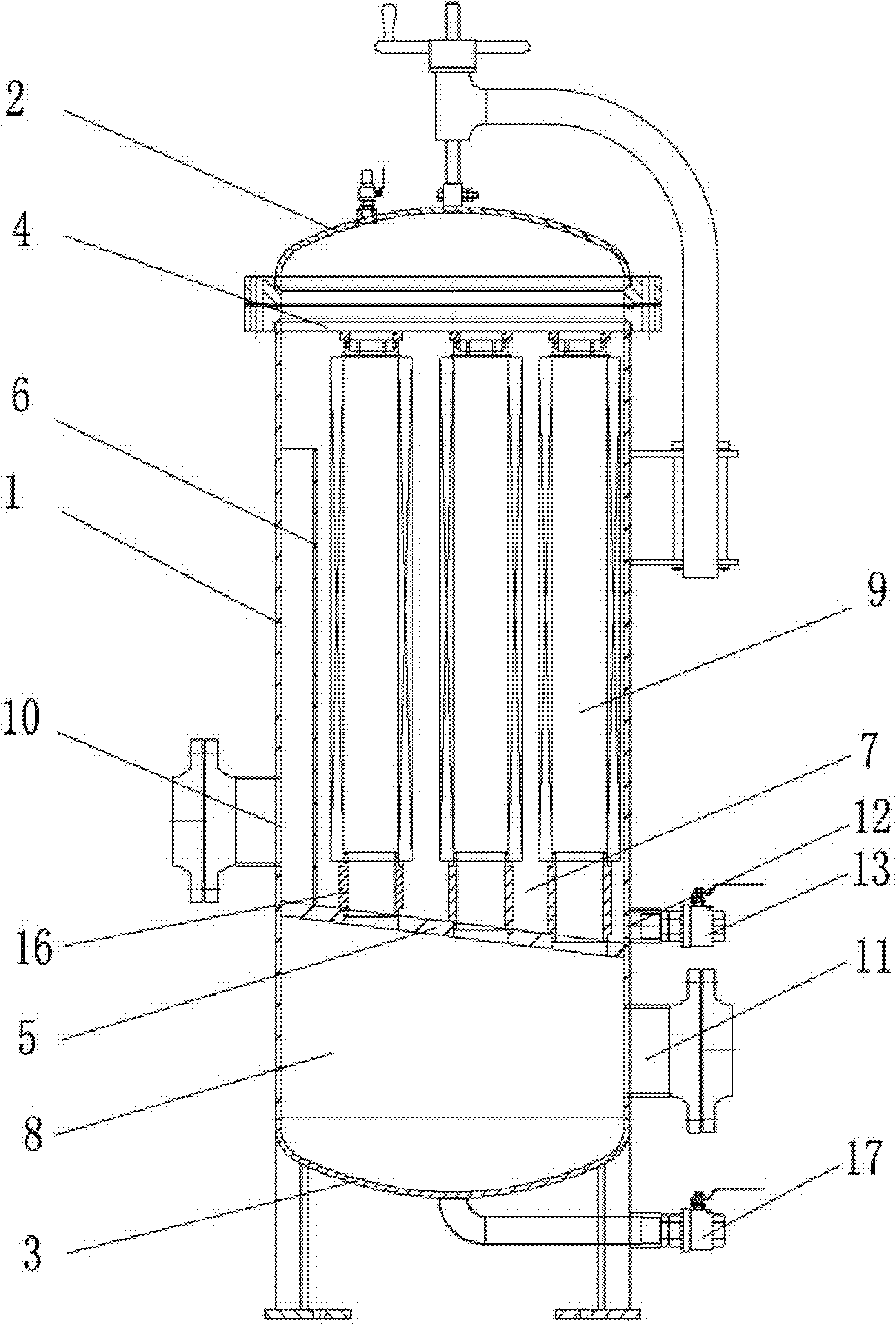
[0022] Such as image 3 , Figure 4 As shown, in addition to the features of the first embodiment, the second embodiment of the present invention is provided with a vertical anti-wash plate 6 located between the filter element 9 and the liquid inlet 10 on the tube plate 5. It is divided into a diversion area 14 and a working area 15 which are connected at the top.


PUM


Abstract

The invention discloses a filter, which comprises a cylinder, an upper seal head, a lower seal head, a pressing plate, a filter element, a filter element seat and a tube plate, wherein the cylinder, the upper seal head and the lower seal head form a can body of which the center is provided with a cavity; the pressing plate is connected with an inner wall at the top end of the cylinder; the tube plate is obliquely arranged and is fixedly connected with the inner wall of the cylinder; the tube plate separates the cavity of the can body into a filtering area and a clear liquid area; the upper end of the filter element is connected with the pressing plate and the lower end of the filter element is connected with the tube plate through the filter element seat; a liquid inlet, a liquid outlet and a drain outlet are formed on a side wall of the cylinder; the liquid inlet is communicated with the filtering area; the liquid outlet is communicated with the clear liquid area; the drain outlet is formed at the lowest end of the tube plate and is communicated with the filtering area; the drain outlet is connected with a drain valve; and an oil outlet valve is arranged at the bottom of the lower seal head. The invention has the advantages that: the filter has good drainage effect and hardly introduces dirt into the clear liquid area in the process of replacing the filter element.

Description

technical field [0001] The invention relates to a filter for filtering impurities in liquids such as oil liquid and cooling liquid. Background technique [0002] The filter in the prior art includes a cylinder with a cavity in the center formed by a cylinder, a top plate and a bottom plate, and the cavity is divided into a filter area and a clean liquid area by a horizontally arranged tube sheet in the cylinder, and the top plate and the tube sheet A filter element is installed between them. The side wall of the cylinder is provided with a liquid inlet, a liquid outlet and a sewage outlet. The liquid inlet and the sewage outlet are connected to the filter area, the liquid outlet is connected to the clean liquid area, and the sewage outlet is set at the bottom of the filter area. When in use, the liquid to be filtered enters the filter area through the liquid inlet, and the liquid to be filtered becomes a net liquid after being filtered by the filter element and enters the n...

Claims


Application Information

Patent Timeline
IPC IPC(8): B01D29/33
Inventor 杨淼
Owner 杨淼
Why Eureka
Try Eureka