Multifunctional closestool

A multi-functional toilet technology, applied in the field of sanitation facilities, can solve the problems of labor cost, ineffective sewage discharge, easy clogging, etc., and achieve the effect of wide flushing range, excellent sewage discharge effect, and not easy to clog

Pending Publication Date: 2022-08-05
余书全
View PDF0 Cites 0 Cited by
  • Summary
  • Abstract
  • Description
  • Claims
  • Application Information

AI Technical Summary

Problems solved by technology

[0003] The existing toilet flushing method is basically to flush water from the drain hole on the inner wall of the toilet, which will prevent some dead corners such as the edge of the toilet ring from being flushed and cause dirt to accumulate. The flushing is carried out at the dead angle position, and because the drainage hole on the inner wall of the toilet is small, it is easy to block, thus affecting the flushing effect. excess water consumption

Method used


Image

  • Multifunctional closestool
  • Multifunctional closestool
  • Multifunctional closestool

Examples


Embodiment 1

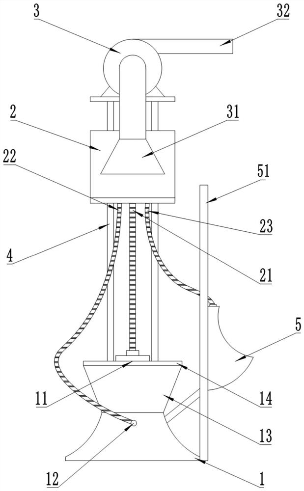
[0036] like figure 1 As shown, the present embodiment provides a multifunctional toilet, including a toilet 1, a water tank 2, an exhaust fan 3 and a bracket 4, the bracket 4 is a steel structure bracket 4, and the toilet 1, the water tank 2 and the exhaust fan 3 are respectively fixed to the bracket 4. The lower, middle and upper parts. The water tank 2 is located 1 meter above the toilet 1. The bottom of the water tank 2 is provided with a first pipeline 21, a second pipeline 22 and a third pipeline 23 respectively. The button for the water outlet of the second pipeline 22 and the third pipeline 23. The exhaust fan 3 is arranged on the top of the water tank 2, and the exhaust fan 3 includes an air inlet pipe 32 and an air exhaust pipe 33. Driven by the motor, the air is sucked by the air inlet pipe 32 and discharged from the exhaust pipe 33.

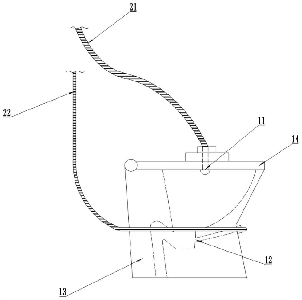
[0037] like figure 2 As shown, the sewer pipe of the toilet 1 is a siphon type pipe. The toilet 1 includes a bucket body 13 and a...

Embodiment 2

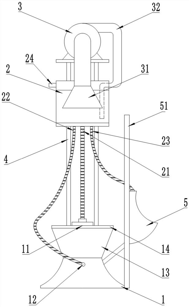
[0043] like image 3 As shown, the difference between the second embodiment and the first embodiment is that the exhaust pipe 33 of the exhaust fan 3 extends downward and extends below the liquid level in the water tank 2. The top of the water tank 2 is also provided with an air outlet 24. The air outlet 24 is of an electronically controlled opening and closing type, and the air outlet 24 is also provided with an activated carbon filter, which can filter the gas discharged from the air outlet 24 . A solid toilet-cleaning block is placed in the water tank 2 , and the main components of the solid toilet-cleaning block include hydrochloric acid (or adipic acid) and fragrance, and an air pressure sensor is also installed in the water tank 2 . The front of the men's urinal 5 is provided with an infrared sensor, which can perform infrared induction automatic flushing. The rest of the structure is the same as that of the first embodiment.

[0044] The use process of this embodiment...

Embodiment 3

[0048] like Figure 4 As shown, the difference between the third embodiment and the second embodiment is that the toilet 1 is also provided with a toilet paper processing bucket 6, the toilet paper processing bucket 6 is cylindrical, and the bucket usually contains water that accounts for one-third of the volume, and the top It is semi-closed and is provided with a flip cover 63, and the area of ​​the flip cover 63 is about one-third of the area of ​​the top. A first spout 61 is provided at the top center of the toilet paper processing bucket 6, and a second spout 62 is provided on the bottom side wall. The bottom of the water tank 2 is also provided with a fourth pipeline 25. The fourth pipeline is a three-way pipeline, which is respectively connected to the bottom of the water tank 2, the first spout 61 and the second spout 62, and the fourth pipeline 25 passes through the first spout. 61 and the second spout 62 are respectively fixed at the top and bottom positions of the ...


PUM


Abstract

The invention relates to the technical field of sanitary facilities, and discloses a multifunctional closestool which comprises a closestool body, a water tank, an exhaust fan and a support, the closestool body, the water tank and the exhaust fan are all fixed to the support, the water tank is arranged above the closestool body, the exhaust fan is arranged above the water tank, and the closestool body comprises a closestool body and a closestool cover. A first water outlet penetrating through the barrel cover is formed in the middle of the barrel cover, a second water outlet penetrating through the barrel body is formed in the side wall of the hole in the barrel body, the water tank is communicated with the first water outlet and the second water outlet through pipelines, and a shower nozzle is installed at the position of the first water outlet in the inner side of the barrel cover. The closestool has the effects of being excellent in sewage discharging effect and wide in flushing range, the complexity of separately installing the closestool and the exhaust system can be avoided, and time and labor are saved.

Description

technical field [0001] The invention relates to the technical field of sanitary facilities, in particular to a multifunctional toilet. Background technique [0002] As a sanitary ware, the toilet is more and more widely used in both urban and rural areas. At present, the flushing methods of toilets mainly include straight-flushing and siphon. The siphon type is that when the water rotates and rushes down through the pipe, it will generate a suction force for sewage discharge. [0003] The existing toilet flushing methods basically use water from the inner wall drainage holes of the toilet for flushing, so that some dead corners such as the edge of the toilet seat cannot be flushed and cause filth accumulation. The dead angle is flushed, and because the drainage hole on the inner wall of the toilet is small, it is easy to block, which affects the flushing effect. The above flushing method cannot achieve the effect of sewage discharge when the flushing pressure of the water t...

Claims


Application Information

Patent Timeline
IPC IPC(8): E03D9/05E03D9/00E03D1/012E03D5/10E03D5/01E03D13/00
CPCE03D9/05E03D9/002E03D9/005E03D1/012E03D5/105E03D5/01E03D13/005
Inventor 余书全
Owner 余书全
Why Eureka
Try Eureka