Closestool with pressurizing drainage device

A technology for drainage devices and toilets, which is applied in water supply devices, flushing toilets, sanitary equipment for toilets, etc. It can solve the problems that affect the water-saving performance of siphon toilets, poor water-saving effects, and large water consumption, and achieve sewage discharge The effect is strengthened, the effect of sewage discharge is obvious, and the effect of saving water

Inactive Publication Date: 2014-01-22
XIAMEN AXENT
View PDF5 Cites 0 Cited by
  • Summary
  • Abstract
  • Description
  • Claims
  • Application Information

AI Technical Summary

Problems solved by technology

However, compared with the straight-flush toilet, the water-saving effect of the traditional siphon toilet is not good. That is, it takes a long time and a large amount of water to form a large water level difference between the toilet and the sewage pipe to flush the toilet, which will cause excessive water consumption, which will affect the water-saving performance of the siphon toilet

Method used


Image

  • Closestool with pressurizing drainage device
  • Closestool with pressurizing drainage device
  • Closestool with pressurizing drainage device

Examples


no. 1 example

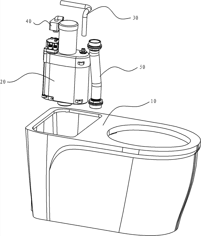
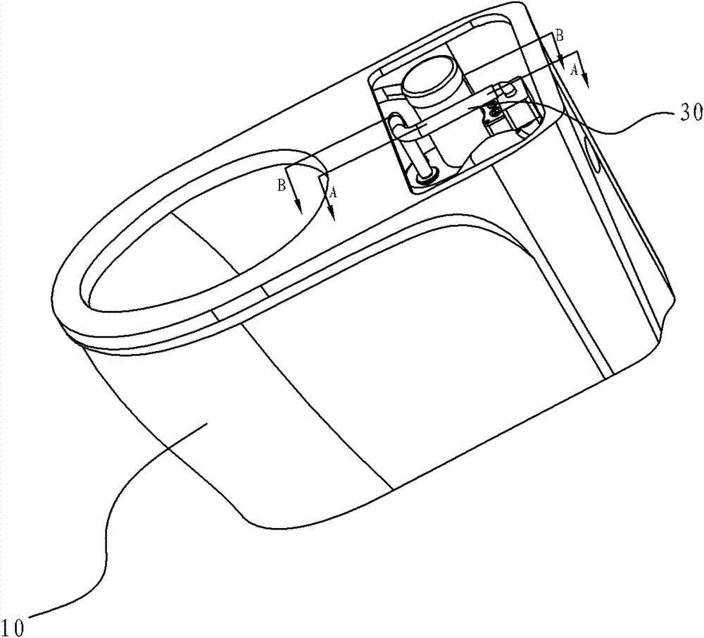
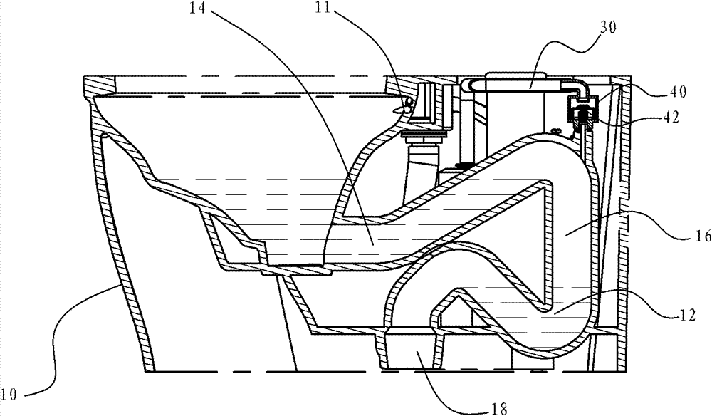
[0028] Such as figure 1 , figure 2 , image 3 As shown, the toilet with a pressurized drainage device according to the present invention includes a toilet body 10 and a pressurized drainage device; the toilet body 10 is provided with a ring washing nozzle 11, an upper trap 14, a lower trap 12, Gas storage pipeline 16, sewage outlet 18, gas delivery pipe 30, gas storage pipeline 16 is located between the upper water trap 14 and the lower water trap 12, and communicates with the upper water trap 14 and the lower water trap 12, the sewage outlet 18 communicates with the lower water trap 12, and the gas delivery pipe 30 communicates with the gas storage pipeline 16.

[0029] Such as image 3 , Figure 4 , Figure 5 As shown, the pressurized drainage device includes a box body 20 and a water inlet and outlet mechanism and a pressure mechanism located in the box body 20. The water inlet and outlet mechanism includes a water inlet pipe 27, a drain switch 23 and a drain valve 29...

no. 2 example

[0033] Such as Image 6 , Figure 8 , Figure 9 As shown, the difference between this embodiment and the first embodiment is that the upper end of the box body 20 is also provided with a second air port 31'. The installation position of the second air port is not limited to this, and it can also be installed on the air pipe or on the buffer. The front end; the second air port 31' is provided with an air supply check valve 60 and an air port spring 62, the air supply check valve 60 is used to control the air entering the second air port 31', and the air port spring 62 is arranged under the air supply check valve 60 and in a preloaded state.

[0034] Such as image 3 , Figure 7 , Figure 8As shown, when the second chamber 25 of the box body 20 enters water through the water inlet pipe 27, the piston assembly 21 moves upward, the space of the first chamber 24 becomes smaller, the space of the second chamber 25 becomes larger, and the first chamber The air in the chamber 24...

no. 3 example

[0036] Such as Figure 10 , Figure 11 , Figure 12 As shown, the difference between this embodiment and the first embodiment is that the upper end of the box body 20 is also provided with a second air port 31', and the second air port 31' is provided with an exhaust check valve 60, which is used for exhaust check valve 60. In order to control the discharge of air from the box body 20 , the first air port 31 is provided with an air suction one-way valve 70 , and the air suction one-way valve 70 is used to control air entering the box body 20 from the air delivery pipe 30 .

[0037] Such as image 3 , Figure 11 As shown, when the second chamber 25 of the box body 20 enters water through the water inlet pipe 27, the piston assembly 21 moves upward, the space of the first chamber 24 becomes smaller, the space of the second chamber 25 becomes larger, and the first chamber The air in the chamber 24 is compressed, and both the exhaust one-way valve 60 and the suction one-way va...


PUM


Abstract

The invention discloses a closestool with a pressurizing drainage device, which comprises a closestool body and the pressurizing drainage device. An upper drain trap, a lower drain trap, an air storage pipe and an air supply pipe are arranged on the closestool body. The pressurizing drainage device comprises a box body and a pressurizing mechanism. A first air port is arranged on the box body. The box body is divided into a first chamber and a second chamber. The air supply pipe is communicated with the box body through the first air port. The second chamber of the box body is provided with a drainage outlet. A buffer which is used for preventing water from entering the air supply pipe is arranged between the air supply pipe and the air storage pipe. By adopting the technical scheme, the closestool with the pressurizing drainage device has the beneficial effects that by adopting the design of the buffer, the water in the upper water trap and the lower water trap in the closestool body can be prevented from entering the air feeding chamber of the box body through the air supply pipe and the effect of protecting the pressurizing drainage device is taken. By using the closestool with the pressurizing drainage device, not only can the water be saved, but also the sewage drainage effect is obvious.

Description

technical field [0001] The invention relates to a bathroom product, in particular to a toilet with a pressurized drainage device. Background technique [0002] The structure of the siphon toilet is that the drainage pipe is "∽" type. After the drainage pipe is filled with water, there will be a certain water level difference, and the sewage will be discharged by the suction generated by the flushing water in the sewage pipe of the toilet. Since the flushing and drainage of the siphonic toilet mainly does not rely on the momentum of the water flow, and the water surface in the pool is relatively large, the flushing noise is relatively small. However, compared with the straight-flush toilet, the water-saving effect of the traditional siphon toilet is not good. That is, it takes a long time and a large amount of water to form a large water level difference between the toilet and the sewage pipe to flush the toilet, which will cause excessive water consumption, thereby affectin...

Claims


Application Information

Patent Timeline
Patent Type & Authority Patents(China)
IPC IPC(8): E03D11/02E03D9/16
Inventor 江长发
Owner XIAMEN AXENT
Why Eureka
Try Eureka