Chain brake device

A technology of braking equipment and equipment, which is applied to ships and other directions, can solve problems such as hydraulic system damage and strong waves, and achieve the effect of avoiding transformation

Inactive Publication Date: 2011-08-24
MACGREGOR NORWAY
View PDF9 Cites 14 Cited by
  • Summary
  • Abstract
  • Description
  • Claims
  • Application Information

AI Technical Summary

Problems solved by technology

A particular problem in open water is that strong waves can be generated when raising the anchor, causing greater loads than...

Method used


Image

  • Chain brake device
  • Chain brake device
  • Chain brake device

Examples


Embodiment Construction

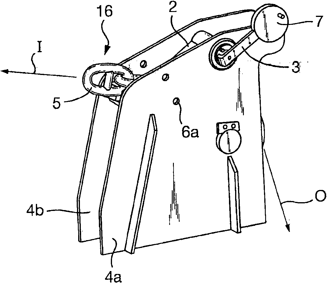
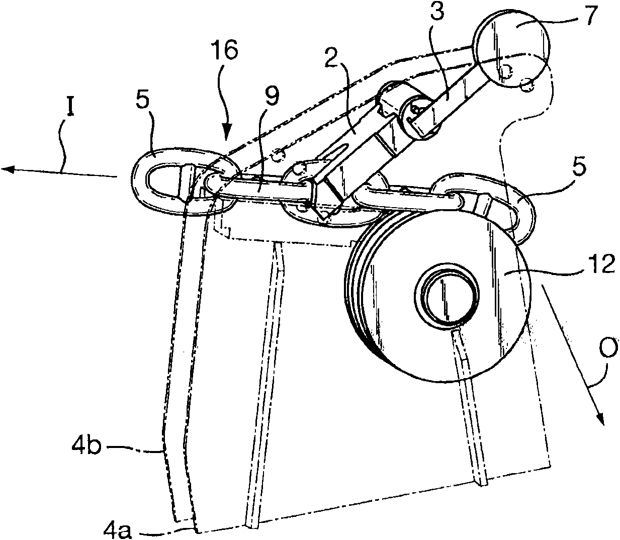
[0031] Referring to the attached drawings, first of all figure 1 and figure 2 , the chain braking device according to the invention comprises a frame which in the described embodiment consists of two upstanding plate elements 4a, 4b which are attached at their lower ends to the deck of the ship by conventional means ( not shown). This device replaces conventional chain brakes and is therefore welded to the deck between the windlass and the hawse barrel. Anchor chain 16 (only a portion of which is shown) extends through the chain braking apparatus, in the inboard direction towards the winch (not shown), indicated by the arrow marked "I", and in the outboard direction towards the hawse barrel ( not shown) and the sea, shown by the arrow marked "O". Thus, when the anchor chain is released from the ship, it moves in the "O" direction, and when it is pulled back, for example in connection with the lifting of the anchor, the chain moves in the "I" direction. These operations ar...


PUM


Abstract

The invention relates to a chain brake device, and concretely discloses a chain brake device used for an anchor chain operated by a capstan, the chain brake device comprises a guide device (14a, b, 15) used for a chain link (5, 9). A chain element (2) can perform operation at a first position in no contact with the chain link, a second position in no brake contact with the chain link, and a third position in a brake contact with the chain link. The chain element (2) further comprises at least a first adjacent device (23a, b) used for abutting against a first chain link (9), and at least a second adjacent device (19a, b) used for abutting against a corresponding static third adjacent device (10a, b) in the chain brake device.

Description

technical field [0001] The invention relates to a device for controlling the movement of a chain. More specifically, the invention relates to a device for braking and locking the movement of an anchor chain, as stated in the preamble of claim 1 . Background technique [0002] There is a trend in the shipping industry to moor ships further out to sea (away from ports and protected waters) than they would otherwise. This is due to the economic and / or operational preferences of ship owners or captains and the fact that ports around the world are becoming more and more congested. [0003] With such an out-of-port mooring, the ship in the waters is exposed to enormous sea forces, which may subject the ship's anchoring system to dynamic loads for which it was not designed. A typical windlass (anchor winch) system is designed to lift the anchor and cable out of water at a depth of approximately 80 to 100 meters (7 to 10% of the cable breaking load) at a rate of 9 meters per minut...

Claims


Application Information

Patent Timeline
IPC IPC(8): B63B21/18
CPCB63B21/04B63B21/16B63B21/18
Inventor H·莫伯格J·霍维克K·H·奥德加德
Owner MACGREGOR NORWAY
Why Eureka
Try Eureka