Handle hanger

A suspension and handle technology, applied in the direction of hand-held tools, manufacturing tools, etc., can solve problems such as tipping

Active Publication Date: 2011-08-24
LEIFHEIT
View PDF5 Cites 1 Cited by
  • Summary
  • Abstract
  • Description
  • Claims
  • Application Information

AI Technical Summary

Problems solved by technology

The disadvantage of the suspension device is that the handle tips over when it rests on a vertical surface, such as a wall or a wardrobe, especially when the handle is arranged in the form of a universal joint on the broom head

Method used


Image

  • Handle hanger
  • Handle hanger

Examples


Embodiment Construction

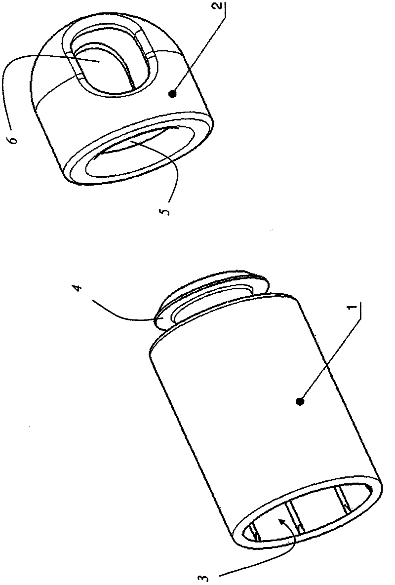
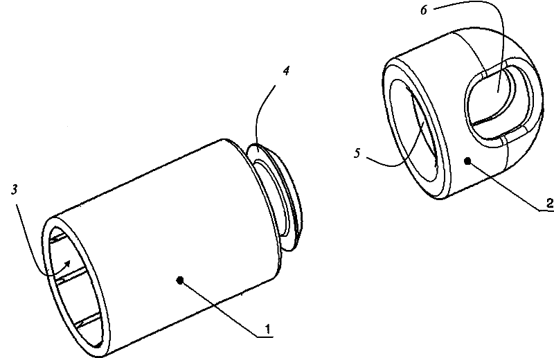
[0013] The drawing shows a disassembled view of the handle suspension of the present invention, which has a holding member 1 which can be fixed on the end of a handle not shown, such as the end of a broom handle. The holding part 1 has an opening 3 into which the handle can be inserted. The fixing on the handle can be effected, for example, by clamping fit or by bonding. A terminal member 2 is provided on the holding member 1, and the terminal member has a surface with high static friction. The holding part 1 has a bulge 4 on the end facing away from the opening 3, which bulge interacts with the groove 5 of the terminal part 2 which surrounds the inside. The groove ensures that the holding part 1 and the terminal part 2 are reliably connected to each other, but can rotate relative to each other. The terminal part 2 has a through hole 6 for hooking.

[0014] The invention has been described with reference to a particular embodiment. However, it is obvious that a large number o...


PUM


Abstract

A two-piece handle hanger comprises a holding part (1) that can be connected to an end of a handle, for example the end of a broomstick, and an end part (2) arranged on the holding part (1), wherein the end part (2) has a surface with high static friction. In one particular embodiment, the end part (2) and the holding part (1) can be rotated relative to each other and have surfaces with different static friction.

Description

Technical field [0001] The invention relates to a handle hanger, which has a holding part and a terminal part arranged on the holding part. The holding part can be fixed on the end of the handle, for example, can be fixed on the end of the broom handle. Background technique [0002] DE 78 231 136 discloses an appliance handle with a two-part suspension device arranged on the free end, wherein one part has at least one circumferential groove, and the other part is inserted into it by means of at least one tab Slot. The disadvantage of the suspension device is that the handle tilts when it leans on a vertical surface such as a wall or a wardrobe, especially when the handle is arranged on the broom head in the form of a universal joint. Summary of the invention [0003] The task of the present invention is to provide a handle hanger, which allows the handle or handle appliance (the handle hanger is fixed on the handle appliance) to be able to lean on the vertical without the risk of...

Claims


Application Information

Patent Timeline
IPC IPC(8): B25G1/10
CPCB25G1/10
Inventor K-J·菲舍尔D·岑斯
Owner LEIFHEIT
Why Eureka
Try Eureka