Injection molding device and injection molding method
A technology of injection molding and injection molding, which is applied in the field of injection molding devices, can solve problems such as repeated trials and designer experience, and achieve the effect of improving stability and quality
- Summary
- Abstract
- Description
- Claims
- Application Information
AI Technical Summary
Problems solved by technology
Method used
Image
Examples
no. 1 approach
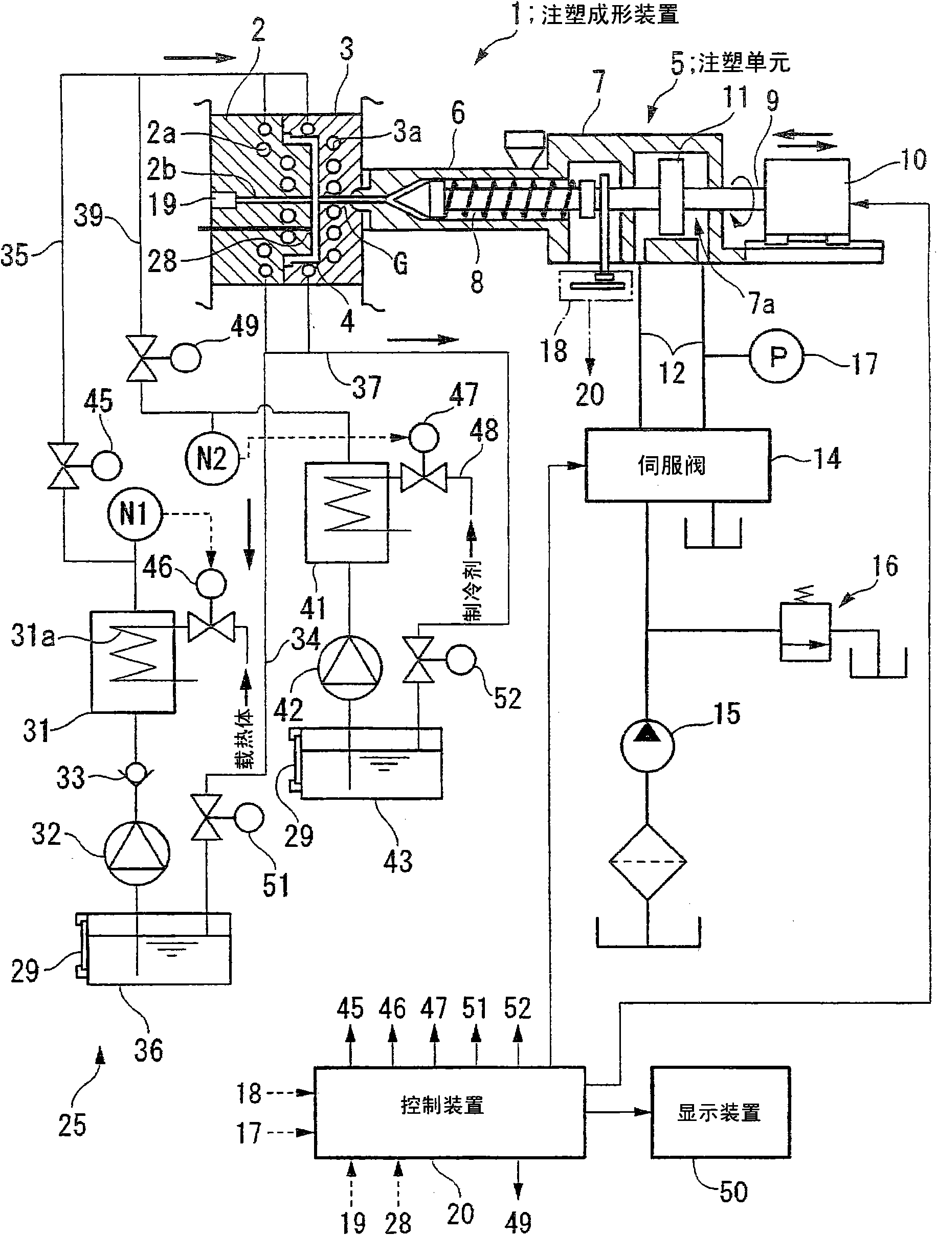
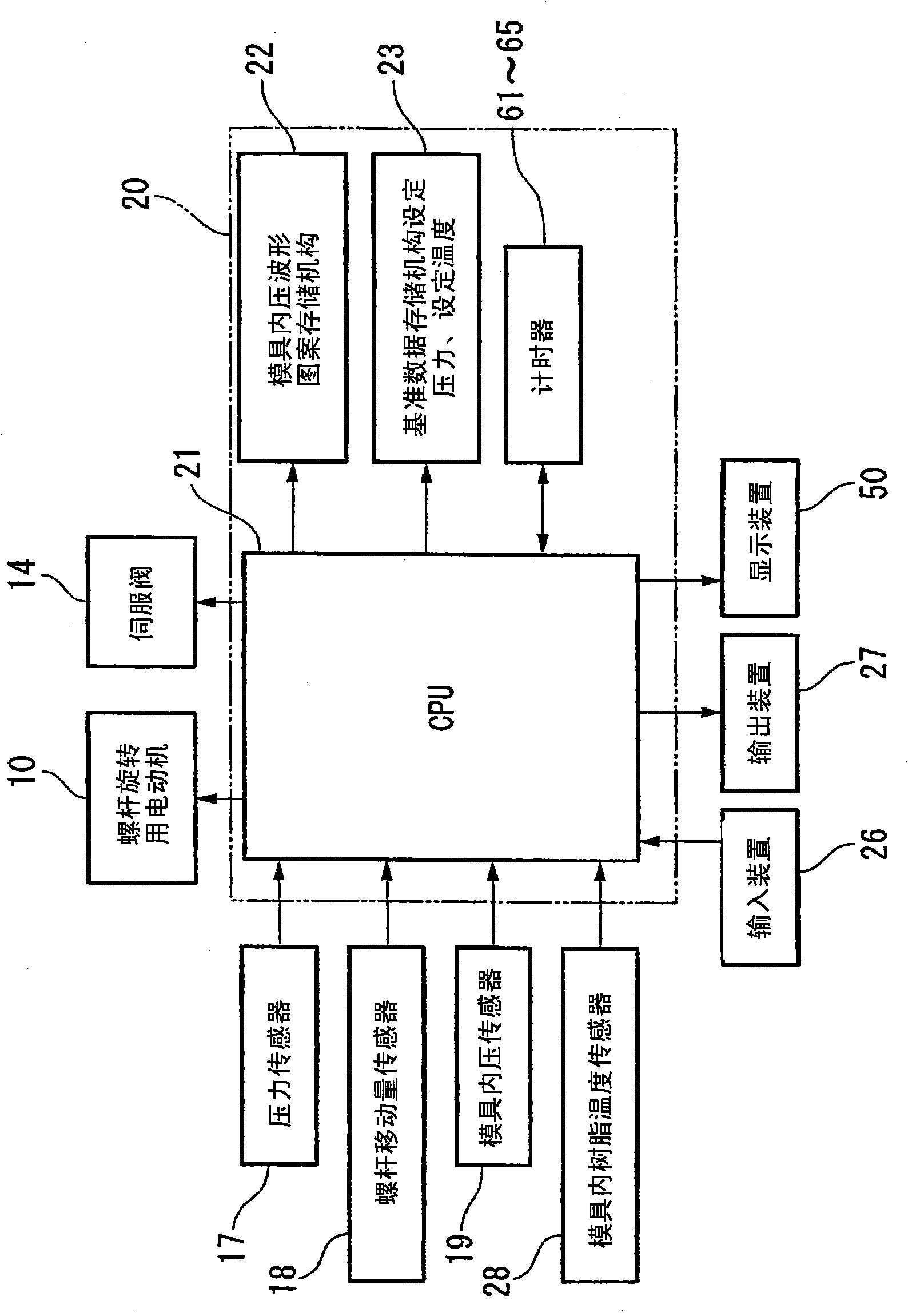
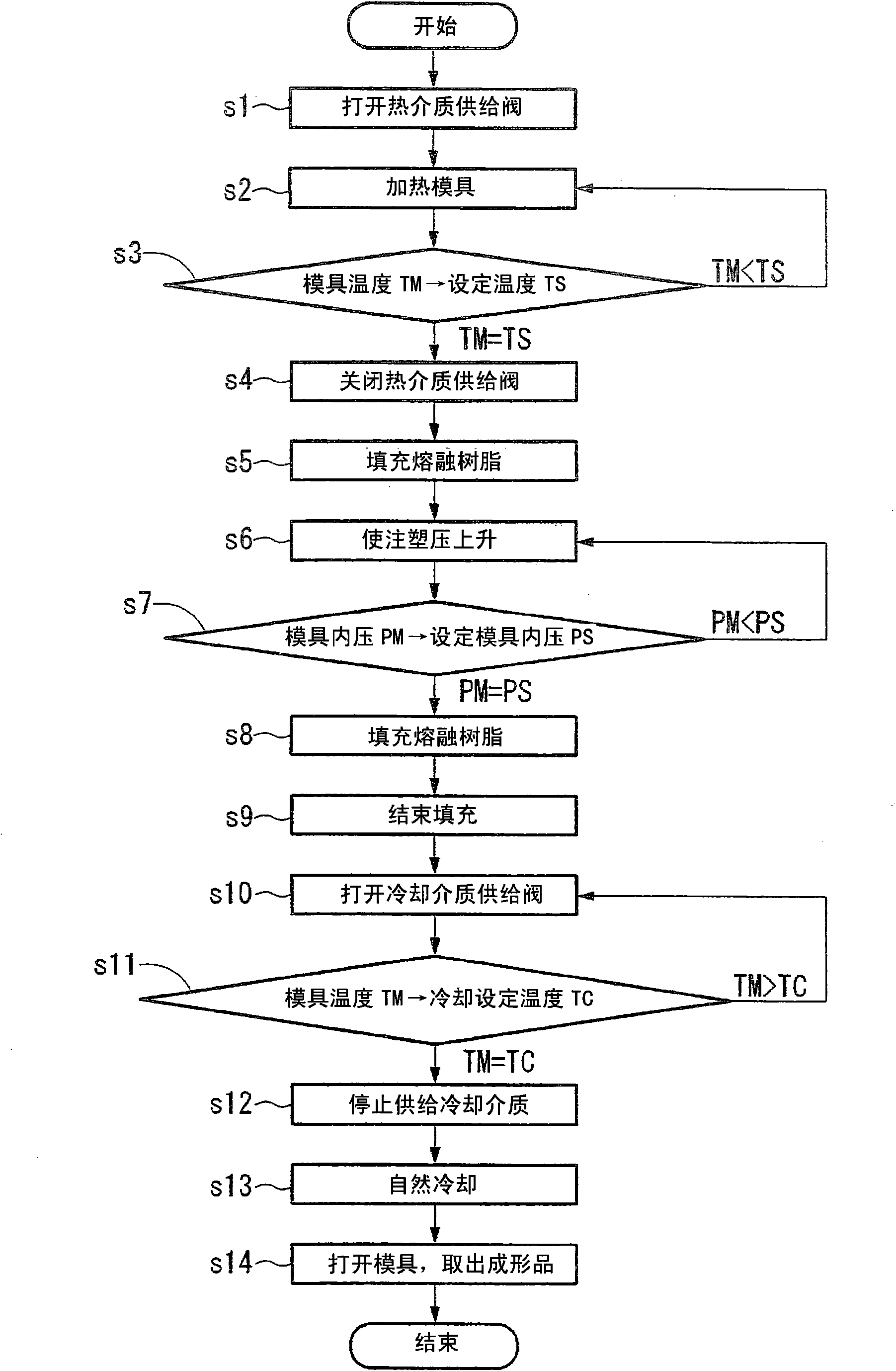
[0044] figure 1It is a schematic diagram of an injection molding device equipped with a hydraulic injection unit capable of implementing the molding method according to the first embodiment of the present invention and a mold heating and cooling control circuit, figure 2 yes means figure 1 A block diagram of the control elements of the mold temperature and mold internal pressure control device included in the mold heating and cooling control circuit, image 3 is used figure 1 Schematic diagram of the mold heating and cooling control loop for injection molding. It should be noted that the mold shown in the illustration is in a state where a cavity has been formed.
[0045] exist figure 1 Among them, an injection molding apparatus 1 includes a movable mold 2 and a fixed mold 3 for obtaining a molded product of a desired shape. The movable mold 2 is fixed to a movable platen (not shown) of the mold clamping device, and the fixed mold 3 is fixed to a fixed platen (not sh...
no. 2 approach
[0094] Figure 5 It is a diagram showing an example of the display of the image display device 50 according to the second embodiment of the present invention, and is a diagram illustrating the first correlation map 81 . Components that are the same as those in the above-mentioned structure are denoted by the same reference numerals and description thereof will be omitted.
[0095] Figure 5 The shown first correlation graph 81 is a graph showing the relationship between the mold temperature TM and time t in one molding cycle, and shows the set value of the switching time (A at the start of filling to D at the end of the holding pressure) together with the correlation. . In this first correlation diagram 81 , the time when the temperature rise of the mold starts is set as the initial time t0.
[0096] According to this display structure, the relationship between the mold temperature TM and the injection operation can be clearly observed, so it is easy to study the factors of...
no. 3 approach
[0103] Figure 7 It is a diagram showing an example of the display of the image display device 50 according to the third embodiment of the present invention, and is a diagram showing a configuration in which the first correlation diagram 91 and other types of correlation diagrams are displayed side by side so that the diagrams can be compared. In addition, the same code|symbol is attached|subjected to the structural element similar to the above-mentioned structure, and description is abbreviate|omitted.
[0104] Specifically, the first correlation diagram 91 , the fourth correlation diagram 84 , and the second correlation diagram 82 are displayed from the bottom to the top of the image display device 50 .
[0105] The first correlation diagram 91 is substantially the same as the first correlation diagram 81 , but differs in displaying the heating target temperature TM1 and the cooling target temperature TM2 of the molds 2 and 3 stored in the control device 20 .
[0106] The s...
PUM
 Abstract
Description
Claims
Application Information
 - R&D
- Intellectual Property
- Life Sciences
- Materials
- Tech Scout
- Unparalleled Data Quality
- Higher Quality Content
- 60% Fewer Hallucinations
Browse by: Latest US Patents, China's latest patents, Technical Efficacy Thesaurus, Application Domain, Technology Topic, Popular Technical Reports.
© 2025 PatSnap. All rights reserved.Legal|Privacy policy|Modern Slavery Act Transparency Statement|Sitemap|About US| Contact US: help@patsnap.com


