Improvements in or relating to rolls

A technology of dehydration roll, bottom layer, applied in the treatment of textile materials, liquid/gas/vapor removal with squeeze roll, squeezer, etc.

Inactive Publication Date: 2011-09-07
RICHARD HOUGH LTD
View PDF0 Cites 3 Cited by
  • Summary
  • Abstract
  • Description
  • Claims
  • Application Information

AI Technical Summary

Problems solved by technology

[0007] However, prior art rubber coated squeeze rolls of the type described above are not without problems and although they have been found to provide reasonable results when used in textile dehydrators, considerable nip pressures are still required, to provide acceptable extrusion properties

Method used


Image

  • Improvements in or relating to rolls
  • Improvements in or relating to rolls

Examples


Embodiment Construction

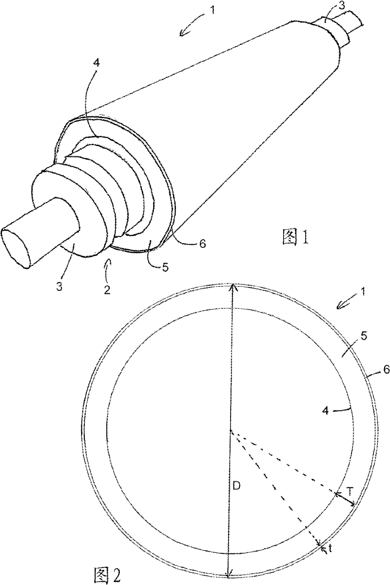
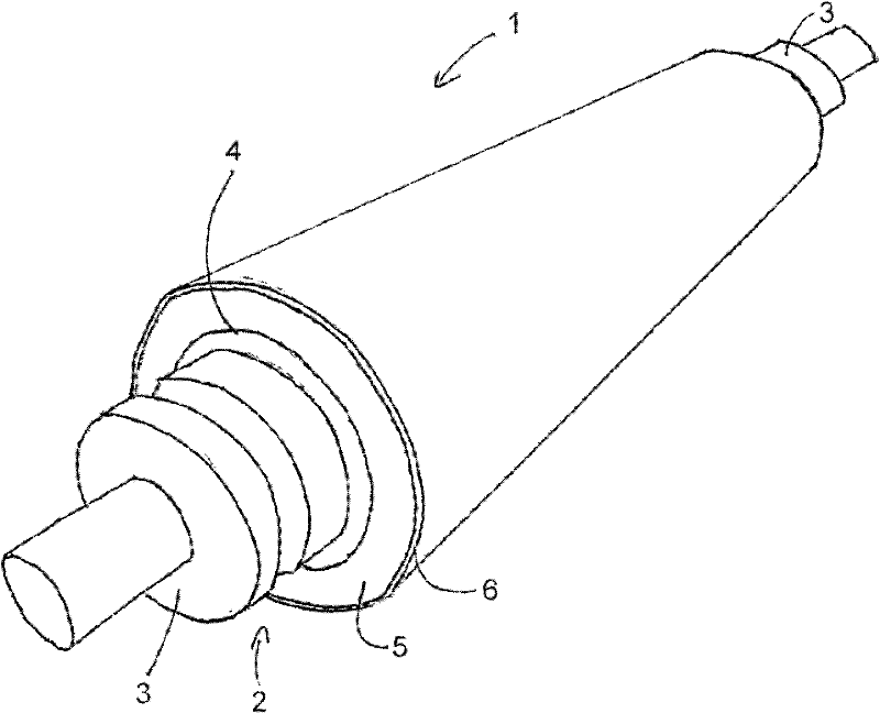
[0025] First refer to figure 1 , shows a squeeze roll 1 according to the invention. The roll comprises an elongated central shaft 2, usually made of solid metal, and most preferably steel. The shaft 2 is provided at both ends with short journals 3 configured for engagement with and supported by cooperating bearings provided in the dehydrator (not shown). It will be clear that the shaft 2 may be made of solid metal or tubular metal, or in a form comprising a solid metal core disposed within a protruding metal tube, as is known for providing variable pressure rolls or anti-deflection rolls. Alternatively, the shaft may be made of composite material such as carbon fiber material.

[0026] Between the two journals 3 the shaft 2 has an elongated central portion 4 with a substantially uniform circular cross-section.

[0027] Around the central roller portion 4 of the shaft 2 is provided an elastic bottom layer 5 formed of elastic material, which thus has a generally tubular confi...


PUM


Abstract

There is disclosed a de-watering squeeze roll (1) which is particularly-intended for use in the watering operations in textile industries. The roll comprises a shaft (4), a relatively thick resilient sub-layer provided around the shaft, and a relatively thin resilient outer cover (6) provided around the sub- layer. The sub-layer has a hardness greater than the hardness of the outer cover such that the sub-layer is formed from material having a Shore A hardness of between (85) and (105) whilst the outer cover is -formed from material having a Shore A hardness of between (60) and (80).

Description

technical field [0001] The invention relates to a roll and a device comprising the roll. The invention relates in particular to squeeze rolls and related equipment suitable for use in the textile industry. Background technique [0002] It is known in the textile industry to use squeeze rolls to mechanically dry wet textiles. Traditionally, rubber-coated squeeze rolls are used for this purpose in textile handling machinery such as extruders, dewaterers, wringers, padders, centrifuges and presses. It should also be clear that rolls according to the invention can be used for dewatering purposes in the paper industry where suction and press rolls are used. [0003] A conventional rubber-covered roll includes a central metal shaft with journals at each end. An elastic covering material is arranged on the shaft, and the radial thickness of the elastic material is generally between 10mm and 20mm. While natural rubber can be used for elastic coverings, synthetic elastomeric subs...

Claims


Application Information

Patent Timeline
Patent Type & Authority Applications(China)
IPC IPC(8): D06C15/08D06F47/00
CPCD06B15/02D06F47/00D06B23/021F16C13/00F16C2340/00D06F45/22D06C15/08
Inventor 安东尼·约翰·阿什顿
Owner RICHARD HOUGH LTD
Why Eureka
Try Eureka