Slide linkage structure for drawers

A sliding rail connection and drawer technology, which is applied to drawers, furniture parts, household appliances, etc., achieves the effects of low production precision requirements, simple and reasonable structure, and guaranteed reliability.

Active Publication Date: 2013-04-10
伍志勇
View PDF6 Cites 0 Cited by
  • Summary
  • Abstract
  • Description
  • Claims
  • Application Information

AI Technical Summary

Problems solved by technology

[0003] The object of the present invention is to provide a drawer slide rail connection structure with simple and reasonable structure, reliable connection, no shaking, zero clearance, and low production precision requirements, so as to Overcome deficiencies in existing technologies

Method used


Image

  • Slide linkage structure for drawers
  • Slide linkage structure for drawers
  • Slide linkage structure for drawers

Examples


no. 1 example

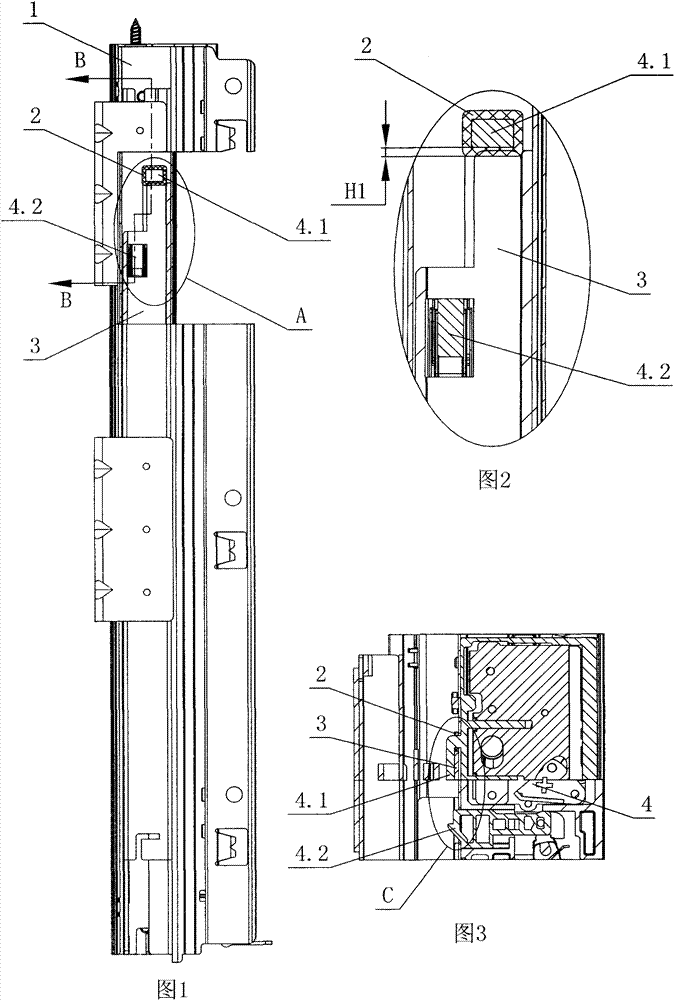
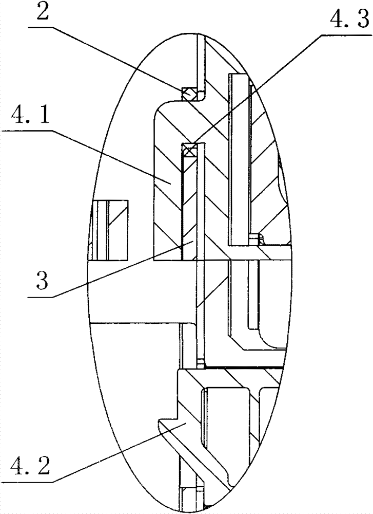
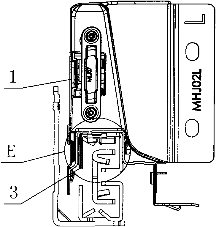
[0030] see Figure 1-Figure 8 , the drawer slide rail connection structure includes a drawer side panel 1 with a panel adjustment device 4 inside, and the front and rear sides of the bottom of the panel adjustment device are respectively provided with a catch hook 4.1 that prevents the moving rail 3 of the slide rail from advancing and a lock that prevents the moving rail from retreating. Tongue 4.2, the catch hook and the lock tongue protrude from the bottom of the side plate of the drawer and connect with the moving rail; the front end of the top of the moving rail is inserted into the catch hook, the front end face 3.1 of the moving rail is in contact with the inner end face 4.3 of the catch hook, and the rear of the front face of the moving rail corresponds The dead bolt is provided with a stop hole 3.2. A gap eliminating component is arranged between the front end surface 3.1 of the moving rail and the inner end surface 4.3 of the retaining hook.

[0031] The gap elimina...

no. 2 example

[0034] see Figure 9-Figure 12 , The gap eliminating component is a cushion 2' made of soft material, which is fixedly connected with the inner end surface 4.3 of the retaining hook in advance by an adhesive. The distance between the front end surface of the lock tongue 4.2 and the inner end surface 4.3 of the retaining hook is L1, the distance between the front end surface of the stop hole 3.2 and the front end surface 4.1 of the moving rail is L2, and the thickness of the cushion 2' is H2; among them, L1 - H2≤L2

[0035] The above cushion 2' can also be fixedly connected to the front end surface 4.1 of the moving rail in advance through an adhesive, then L2L2. Other unmentioned parts are the same as the first embodiment.


PUM


Abstract

The invention discloses a slide linkage structure for drawers, which comprises a drawer side plate, the inside of the drawer side plate is provided with a panel adjusting device, the front and rear side plates of the bottom part of the panel adjusting device are respectively provided with a stop hook for preventing a movable rail of a slide rail from going forward and a locking dog for preventing the movable rail from drawing back, and the stop hook and the locking dog are protruded from the bottom part of the drawer side and connected with the movable rail; the front end of the top part of the movable rail is inserted into the stop hook, the front end face of the movable rail is pressed against the internal end face of the stop hook, and a position which is arranged at the rear part of the front end face of the movable rail and corresponding to the position of the locking dog is provided with a backstop hole; and a gap eliminating component is arranged between the front end face of the movable rail and the internal end face of the stop hook. The gap eliminating component is at least arranged on the internal end face of the stop hook; or the gap eliminating component is at least arranged on the front end face of the stop hook. In the invention, the gaps between the front end face of the movable rail and the internal end face of the stop hook are eliminated by using the gap eliminating component, thereby ensuring the reliability of linkage between the drawer side and the movable rail. The slide linkage structure for drawers disclosed by the invention has the advantages of simple and reasonable structure, reliable linkage, not rocking, zero gap, low production precision requirements, and long service life.

Description

technical field [0001] The invention relates to a drawer slide rail connection structure. Background technique [0002] The existing drawer slide rail connection structure includes a drawer side panel with a panel adjustment device inside, and the front and rear sides of the bottom of the panel adjustment device are respectively provided with a catch hook to prevent the moving rail of the slide rail from advancing and a lock tongue to prevent the movable rail from retreating. And the lock tongue protrudes from the bottom of the side plate of the drawer and connects with the moving rail; the front end of the top of the moving rail is inserted into the retaining hook, the front end of the moving rail is blocked by the inner end of the retaining hook, and the rear of the front end of the moving rail is provided with a stop hole corresponding to the lock tongue . Under normal circumstances, when the front end of the moving rail is inserted into the hook, when the front end of ...

Claims


Application Information

Patent Timeline
Patent Type & Authority Patents(China)
IPC IPC(8): A47B88/04A47B88/427A47B88/95
Inventor 伍志勇
Owner 伍志勇
Why Eureka
Try Eureka