
Whole image sound barrier for urban quick lane and tunnel portal

A technology for sound barriers and tunnel entrances, applied in noise absorption devices, buildings, etc., can solve the problems of reducing traffic noise and unsatisfactory noise reduction effects of sound barriers

Active Publication Date: 2011-09-14
SHANGHAI SHIP & SHIPPING RES INST
View PDF4 Cites 25 Cited by
  • Summary
  • Abstract
  • Description
  • Claims
  • Application Information

AI Technical Summary

Problems solved by technology

By setting baffles perpendicular to the road surface on both sides of the road, it is used to block vehicle noise from radiating to the communities on both sides of the road, but due to the three-dimensional propagation of sound waves, part of the noise is diffracted across the top of the sound barrier and reaches the sound receiving point; part of the noise Penetrate the sound barrier to reach the sound-receiving point; part of the noise reaches the sound-receiving point through multiple reflections from the parallel walls of the sound barrier on both sides, especially in big cities where the high-rise buildings on both sides of the road form a "canyon effect", which also indirectly causes noise. However, it is impossible for the sound barrier to be designed to be infinitely high and infinitely long. Therefore, for sound-receiving points that are close to the road and have high floors, ordinary open sound barriers can only make part of the floors of tall buildings in the sound environment. The shadow area cannot significantly reduce traffic noise as a whole, so the noise reduction effect of the sound barrier is often not ideal

Method used


Image

  • Whole image sound barrier for urban quick lane and tunnel portal
  • Whole image sound barrier for urban quick lane and tunnel portal
  • Whole image sound barrier for urban quick lane and tunnel portal

Examples


Embodiment Construction

[0024] The present invention will be further described below in conjunction with the accompanying drawings, and embodiments of the present invention will be given.

[0025] Such as Figure 8 As shown, usually the area where the sound from the sound source 8 can directly reach is called the sound exposure area, and the area where the sound cannot directly reach is called the sound shadow area 3 . The function of the sound barrier 1 is to block the propagation of direct sound, isolate transmitted sound, and sufficiently attenuate diffracted sound. In view of the characteristics of the width of the main road in the city, the proximity of the sound receiving point 4 to the road, the height of the building, and the high noise value, the key to achieving the goal of significant noise reduction is to expand the sound shadow area 3 of the sound barrier to completely block the direct sound. And the sound barrier 1 should have a certain sound-absorbing surface to isolate the transmitte...


PUM

PropertyMeasurementUnit
Thicknessaaaaaaaaaa

Abstract

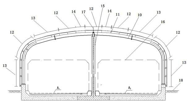
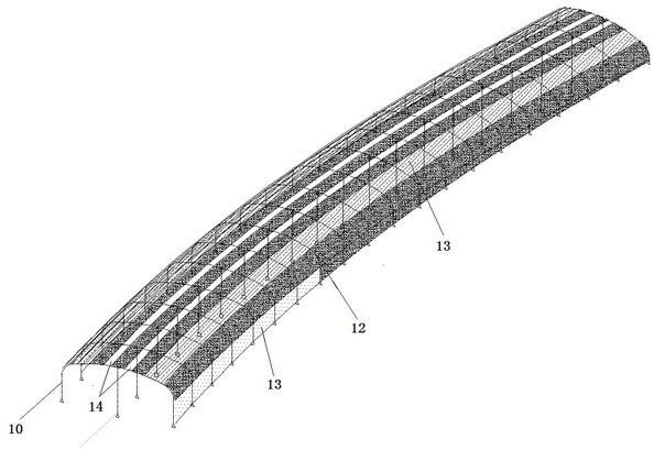
The invention relates to a whole image sound barrier for an urban quick lane and a tunnel portal. The sound barrier is characterized by consisting of gate-type arc steel arch racks arranged in the upper space of a pavement, and a sound barrier main body framework consisting of rigid tie rods for connecting the adjacent arch racks and cross supporting rods, wherein purlines are arranged on the main body framework; and meanwhile, the purlines arranged on the main body framework are used as supports, anti-collision wall contact faces are formed symmetrically on the left and right sides along the central axis of the sound barrier till the pavement, and a sound absorber, a ventilated exhaust part, a sound absorber, a lighting part, a sound absorber and a lighting part are arranged at intervals, so that a full-closed for semi-closed whole image sound barrier structure capable of totally isolating direct sound is formed for a road. The whole image sound barrier for the urban main road can effectively reduce the traffic noise of the urban main road, effectively reduce the reverberation in a sound barrier area and ensure the safety and the comfort degree of a road user, and is a sound barrier suitable for a building dense area nearby the urban main road.

Description

technical field [0001] The invention relates to a sound barrier, in particular to a full-shadow sound barrier used for urban express lanes and tunnel entrances; it belongs to the technical field of urban road noise elimination and reduction. Background technique [0002] In recent years, with the development of road traffic and urban construction, expressways with large traffic volume and high speed have been widely constructed and put into use in cities, and the problem of traffic noise nuisance has become increasingly serious. For the vast majority of old urban areas, road planning cannot be changed, and residential buildings have already taken shape. Due to historical reasons in individual big cities, the situation is even worse. Many residential buildings, hospitals, schools and scientific research institutions are close to the main roads, viaducts and light rails of urban traffic. Complaints soared. [0003] In this case, it is a cost-effective solution to use patchwo...

Claims


Application Information

Patent Timeline
IPC IPC(8): E01F8/00
Inventor 褚国红毛海亮龚辉何金平范谦邱贤锋李晓东郑剑敏
Owner SHANGHAI SHIP & SHIPPING RES INST
Learn More