Device for moving electric energy meter between meter case and multi-epitope tooling board

A technology for transferring devices and electric energy meters, which is applied in the direction of measuring devices, manufacturing tools, and measuring electrical variables, can solve the problems of high labor intensity, low work efficiency, and large investment in equipment, and achieve improved placement accuracy, improved production efficiency, The effect of saving human resources

Active Publication Date: 2011-09-14
STATE GRID ZHEJIANG ELECTRIC POWER +1
4 Cites 22 Cited by

AI-Extracted Technical Summary

Problems solved by technology

[0002] For the convenience of the verification of the single-phase electric energy meter, the single-phase electric energy meter is generally moved from the meter box to the multi-meter tooling board for verification. Most of the above-mentioned transfer work is manual operation, which is labor-intensive and low-efficiency, and is no longer suitable for the production needs of industrial automation; there are also foreign six-degree-of-freedom manipulators introduced to replace manual operations. It is placed on the side, and the two rows of electric energy meters on the multi-meter tooling board must face the detection working surface of the electric energy meter outward, so they are placed head-to-head...

Abstract

A device for moving an electric energy meter between a meter case and a multi-epitope tooling board provided by the invention relates to equipment for moving the electric energy meter, and the invention solves the technological problem that currently most of the electric energy meters are manually operated, and efficiency is low. The device comprises a frame and the device is characterized in that the frame is provided with a transfer bench, a first manipulator and a second manipulator which can move horizontally and vertically, the transfer bench is provided with a holding tank, and is arranged between the first manipulator and the second manipulator, a meter case conveying chain is mounted at one side of the first manipulator of the frame, a multi-epitope tooling board conveying chain is mounted at one side of the second manipulator of the frame, and the second manipulator is also provided with a vertical overturning mechanism and a horizontal rotation mechanism. The invention provides special mechanical automatic equipment used for moving the electric energy meter between the meter case and the multi-epitope tooling board. Advantages of the equipment: production efficiency is improved, manpower resource is saved; precision of placing the electric energy meter on the multi-epitope tooling board is increased; and cost is low, and popularization in a large scale is available.

Application Domain

Technology Topic

Image

  • Device for moving electric energy meter between meter case and multi-epitope tooling board
  • Device for moving electric energy meter between meter case and multi-epitope tooling board
  • Device for moving electric energy meter between meter case and multi-epitope tooling board

Examples

  • Experimental program(1)

Example Embodiment

[0020] Hereinafter, the present invention will be further described through embodiments in combination with the drawings.
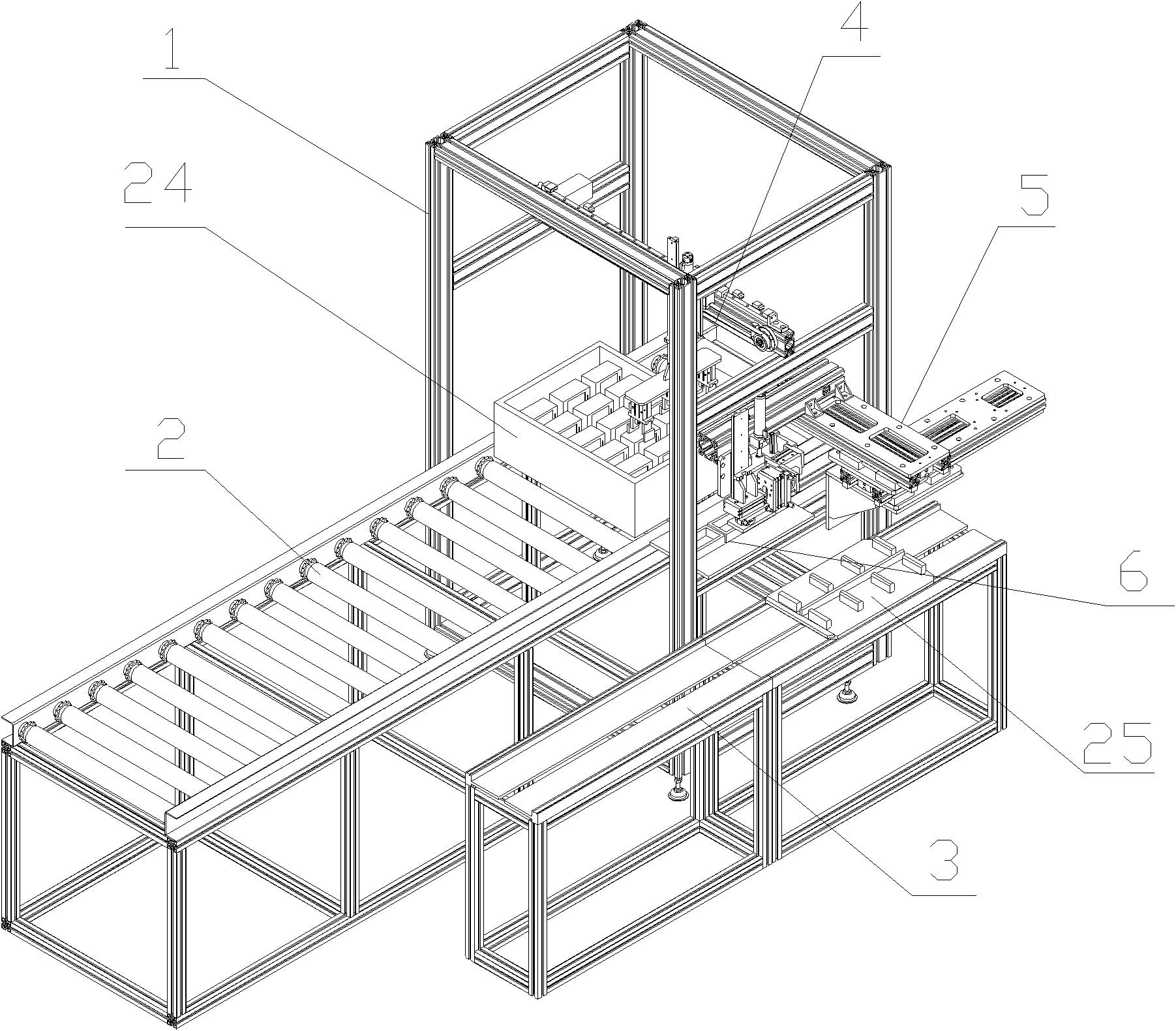
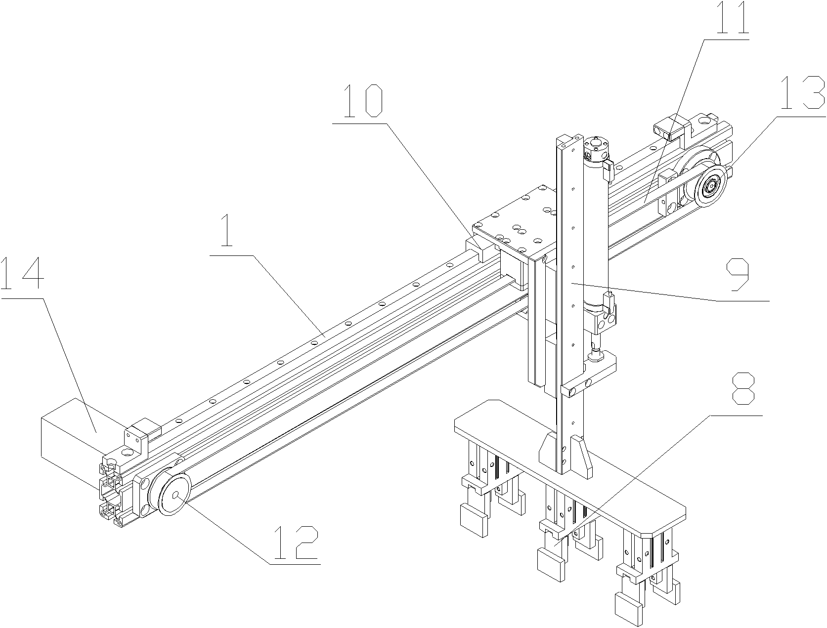
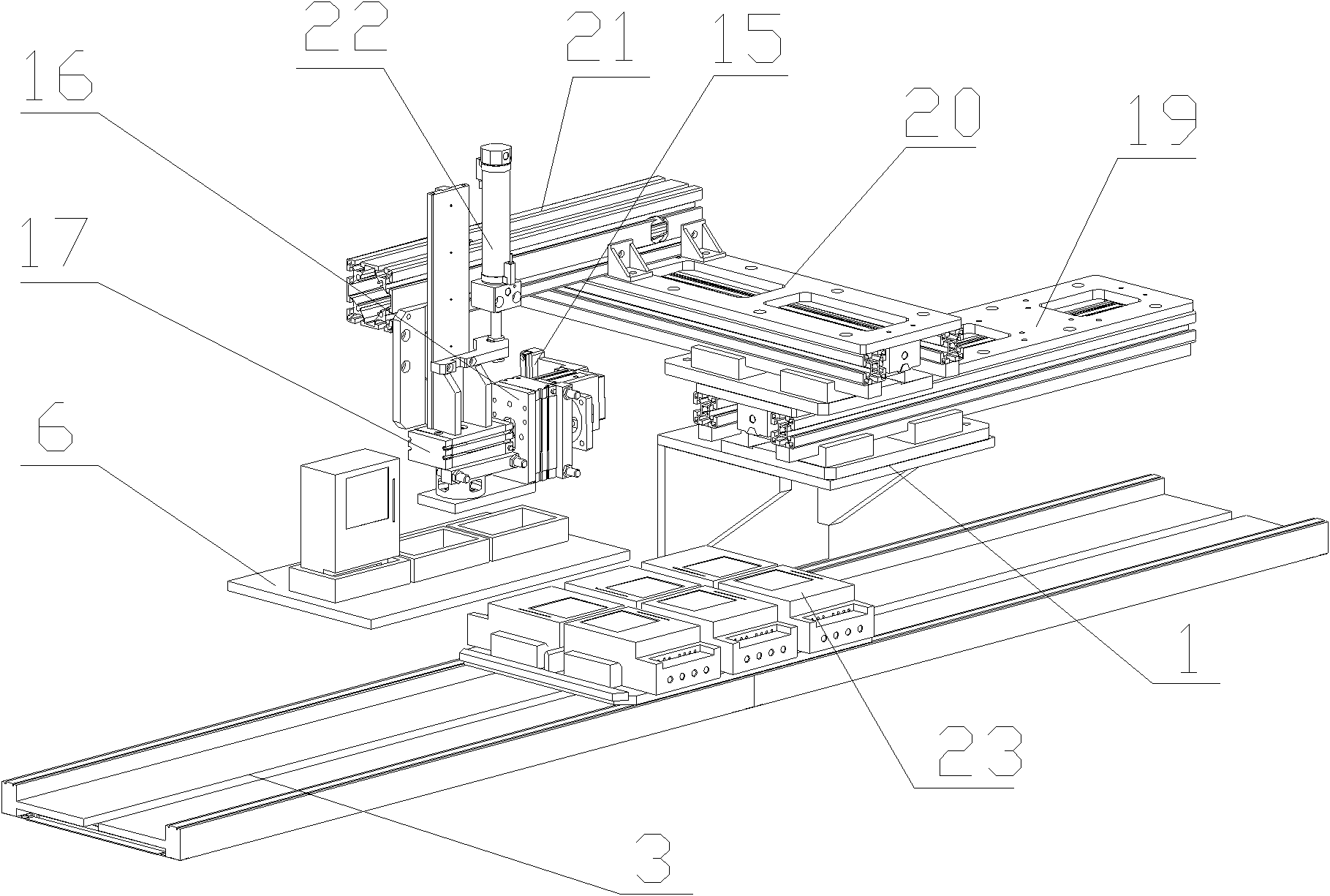
[0021] Such as Figure 1-Figure 4 As shown, the transfer device of an electric energy meter described in this embodiment between the meter box and the multi-meter tooling plate includes a frame 1, on which a first manipulator 4 and a transfer table 6 are sequentially installed. And the second manipulator 5, the first manipulator 4 side of the frame 1 is equipped with a meter box conveyor chain 2, and the second manipulator 5 side of the frame 1 is equipped with a multi-meter tooling plate conveyor chain 3, the Three accommodating grooves 7 are opened on the intermediate turntable 6. The first manipulator 4 includes three pneumatic clamping jaws 8 for clamping the electric energy meter. The pneumatic clamping jaws 8 are arranged on a longitudinal member 9. The member 9 is arranged on a vertical guide rail of a transverse member 10 and is driven by an air cylinder. The transverse member 10 is slidably connected to the frame 1 and is provided with transmission teeth. The timing belt 11 is toothed and connected. The timing belt 11 is sleeved on a driven wheel 13 and a driving wheel 12 connected to a motor 14. The driving wheel 12 and the driven wheel 13 are fixedly connected to the frame 1. The second manipulator 5 includes a clamp 15 for holding the electric energy meter, and the clamp 15 is fixedly connected to a vertical turning mechanism 16, which can turn the vertical electric energy meter 90 degrees into a horizontal position. The mechanism 16 is connected to a horizontal rotating mechanism 17, and the horizontal rotating mechanism 17 can rotate the electric energy meter 180 degrees whose orientation does not match the multi-meter tooling plate 25. The horizontal rotating mechanism 17 is arranged on a vertical lifting mechanism 22. The lifting mechanism is fixed on a sliding block 21, and the sliding block 21 is slidably connected to a cross-shaped horizontal sliding table 18, and the sliding table 18 is composed of a cross-staggered X plate 19 and a Y plate 20, The Y plate 20 is slidably connected to the X plate 19 and is driven by an air cylinder, the X plate 19 is slidably connected to the frame 1 and is driven by another air cylinder, and the slider 21 is slidably connected to the Y plate 20 on. The clamp 15 is a two-ear clamp. The middle section of the clamp 15 expands outwards and is arranged symmetrically. The electric energy meter 23 can be clamped at the extended end, and both the upper and lower sections can position the sliding electric energy meter 23. The vertical turning mechanism 16 is a 90-degree turning mechanism, and the horizontal rotation mechanism 17 is a 180-degree turning mechanism.
[0022] As shown in the figure, the meter box 24 can hold three rows of electric energy meters 23, the multi-meter tooling plate 25 can place two rows of six electric energy meters 23, and the multi-meter tooling plate 25 can put 23 electric energy meters of the outer row of meters. It can be put in by turning it 90 degrees counterclockwise vertically, while the electric energy meter 23 placed in the inner row meter position of the multi-meter tooling plate 25 needs to be turned vertically 90 degrees and rotated 180 degrees horizontally before it can be put in. When the electric energy meter 23 is taken out and placed in the meter box 24, the above operation can be reversed.

PUM

no PUM

Description & Claims & Application Information

We can also present the details of the Description, Claims and Application information to help users get a comprehensive understanding of the technical details of the patent, such as background art, summary of invention, brief description of drawings, description of embodiments, and other original content. On the other hand, users can also determine the specific scope of protection of the technology through the list of claims; as well as understand the changes in the life cycle of the technology with the presentation of the patent timeline. Login to view more.

Similar technology patents

Online quality detection system for printed matter

Owner:昆明瑞丰印刷有限公司

Method for Producing L-Amino Acids Using Bacteria of the Enterobacteriaceae Family

ActiveUS20060141586A1Increase productivityBacteriaHydrolasesEnterobacteriaceae bacteriumL-Arabinose
Owner:AJINOMOTO CO INC

Full-automatic wire harness crimping machine

InactiveCN102074874AIncrease productivityLow energy consumptionConnection formation by deformationBatch productionEngineering
Owner:TIANJIN LIGAN TECH

Classification and recommendation of technical efficacy words

  • Increase productivity
  • Save human resources

Apparati, methods, and compositions for universal microbial diagnosis, detection, quantification, and specimen-targeted therapy

InactiveUS20120129794A1Increase productivityAccurate and rapid and sensitive microbial diagnosis and detection and quantificationAntibacterial agentsBiocidePopulationMolecular Targeted Therapies
Owner:DOWD SCOT E +2
Why Eureka
Try Eureka