Direct inserted light emitting diode (LED) radiating unit and radiating system

A heat dissipation unit and heat dissipation system technology, applied in the direction of electrical components, circuits, semiconductor devices, etc., can solve the problems of high consumption of chemical raw materials, unsatisfactory heat dissipation effect, high labor costs, etc., achieve good heat dissipation effect, simple and reasonable structure, The effect of saving production cost

Inactive Publication Date: 2013-05-15
喻新立
View PDF3 Cites 0 Cited by
  • Summary
  • Abstract
  • Description
  • Claims
  • Application Information

AI Technical Summary

Problems solved by technology

However, the heat dissipation effect of these measures is often not ideal, and it will take up a lot of space, affecting the installation
In addition, it consumes a lot of energy and chemical raw materials from the manufacture of circuit boards to subsequent processing into products, and the labor costs are high. The production and processing cause great pollution to the environment, which contradicts the current concept of energy conservation and environmental protection.

Method used


Image

  • Direct inserted light emitting diode (LED) radiating unit and radiating system
  • Direct inserted light emitting diode (LED) radiating unit and radiating system
  • Direct inserted light emitting diode (LED) radiating unit and radiating system

Examples


Embodiment b2

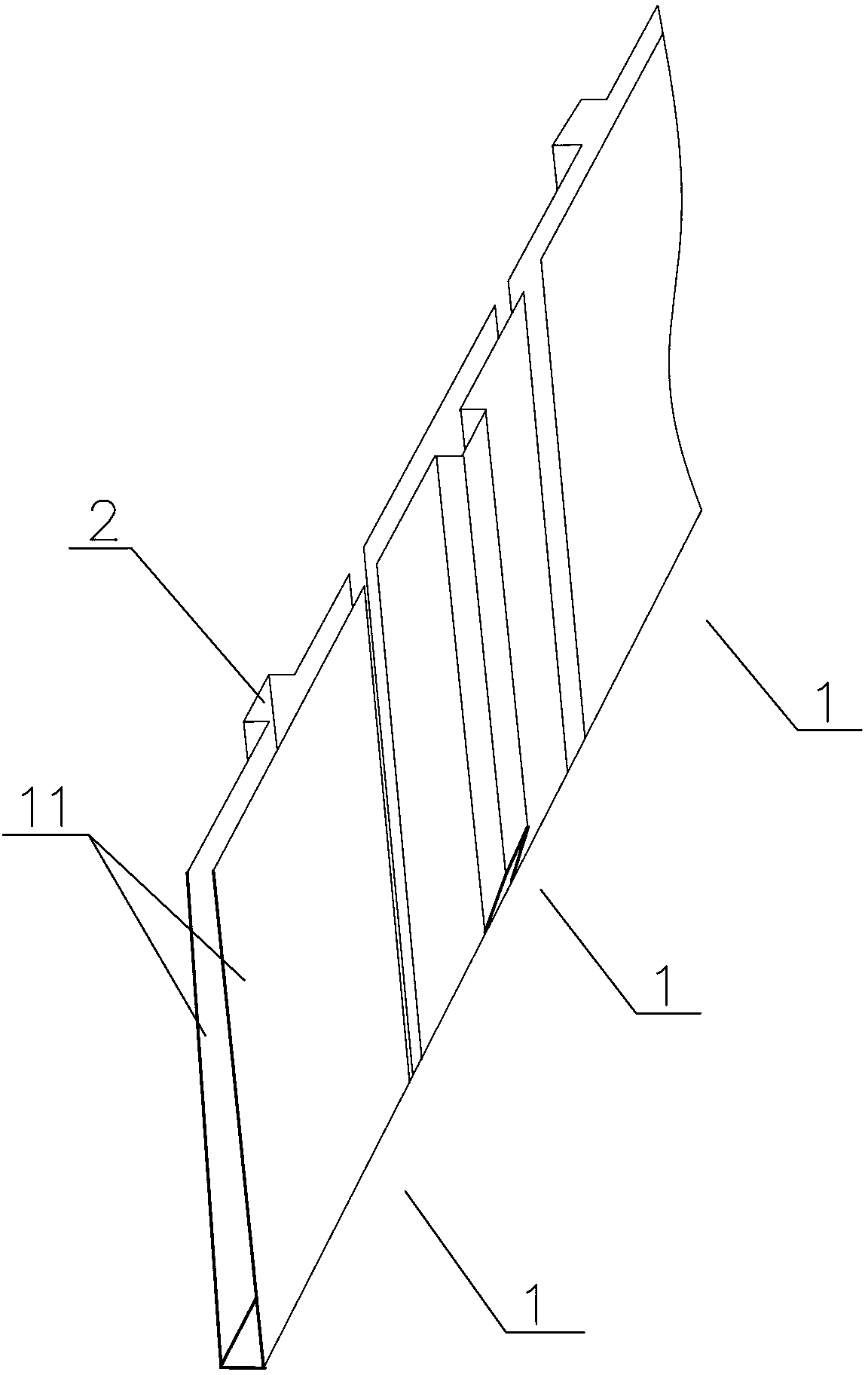
[0033] Embodiment b2: with reference to Figure 4 , connecting the lower extension parts of the plurality of in-line LED cooling fins in sequence as described in embodiment a2, and paying attention to staggering the installation grooves 2 on both sides at intervals to form the in-line LED cooling unit. In actual production, the specific processing details of this in-line LED heat dissipation unit can be the same as that of embodiment b1, and correspondingly, plug pins should be left at the lower extension of the clip 11 to facilitate the connection with peripheral devices. Combination with lighting frame or circuit board mounting frame.

[0034] Embodiment c1 of in-line LED cooling system: refer to Figure 5 , an in-line LED heat dissipation system, which includes a plurality of in-line LED heat dissipation units, and the plurality of in-line LED heat dissipation units are arranged in parallel in multiple rows.

[0035] As a further preferred embodiment, among any two adjace...

Embodiment c2

[0036] Embodiment c2: with reference to Image 6 , making the in-line LED heat dissipation system ring-shaped, that is, the in-line LED heat dissipation unit is in a ring structure, and the multiple in-line LED heat dissipation units are arranged in a multi-layer ring array.

[0037] As a further preferred embodiment, in any two adjacent layers of the ring-shaped in-line LED heat dissipation units, at least two mounting grooves 2 have protruding directions facing each other and facing each other. In some occasions, it may be necessary to arrange a ring-shaped LED array. By making the in-line LED heat dissipation unit ring-shaped and surrounding it in multiple layers, a planar ring-shaped array of multiple installation slots 2 in groups of two is formed. The requirement that the protruding directions of at least two installation grooves 2 in any adjacent two layers of the ring-shaped in-line LED heat dissipation units face each other and face each other is actually the same as ...


PUM


Abstract

The invention discloses a direct inserted light emitting diode (LED) radiating fin. The direct inserted LED radiating fin comprises a metal radiating fin provided with a mounting groove for inserting a direct inserted LED pin. The invention also discloses a direct inserted LED radiating unit comprising a plurality of direct inserted LED radiating fins. The direct inserted LED radiating fins are sequentially connected or directly integrated, and the mounting grooves are staggered at intervals and positioned on two sides of the radiating unit. The invention further discloses a direct inserted LED radiating system. The direct inserted LED radiating system comprises a plurality of columns of direct inserted LED radiating units arranged in parallel, or a plurality of direct inserted LED radiating units in annular structure encircle a multilayer annular array. The metal radiating fin has good radiating effect, and the mounting groove is convenient for inserting and installing the direct inserted LED; the direct inserted LED radiating unit enlarges the radiating area, and increases the radiating efficiency; and the direct inserted LED radiating system further enlarges the radiating area,and can meet various LED arrangement requirements. The invention is widely applied to various occasions for installing the direct inserted LED in large area.

Description

technical field [0001] The invention relates to an LED heat dissipation device, in particular to a heat dissipation fin of an in-line LED, a heat dissipation unit composed of the heat dissipation fins and a heat dissipation system composed of the heat dissipation unit. Background technique [0002] LEDs are usually divided into in-line LEDs and SMD LEDs. In-line LEDs have a lamp cap and two positive and negative pins protruding from the lamp cap; SMD LEDs are square, with positive and negative poles on the two opposite sides. . Compared with traditional light sources, LED has the advantages of green energy saving, low-voltage DC drive, no ultraviolet radiation, small size, long life, stable wavelength, strong luminescence, good light color, and adjustable brightness. However, due to the concentrated heat generated by the LED, the heat dissipation effect is extremely poor. If the heat can not be dissipated in time, it will lead to premature decline of luminescence, accelera...

Claims


Application Information

Patent Timeline
Patent Type & Authority Patents(China)
IPC IPC(8): H01L33/64H01L33/48
Inventor 喻新立喻东颜喻东琳
Owner 喻新立
Why Eureka
Try Eureka