Device for scanning airport pavement foreign object

A technology for scanning devices and foreign objects, applied in the directions of cameras, supporting machines, mechanical equipment, etc., can solve the problems of low detection function, sudden increase in false alarm rate, inability to meet actual use requirements, etc., to achieve high detection accuracy and improve reliability. Effect

Inactive Publication Date: 2011-09-14
CHANGCHUN UP OPTOTECH
View PDF3 Cites 12 Cited by
  • Summary
  • Abstract
  • Description
  • Claims
  • Application Information

AI Technical Summary

Problems solved by technology

The main shortcomings are: first, the smallest foreign object that can be detected is too large (20 mm), which cannot meet the actual use needs; second, the optical imaging technology is greatly affected by rainy weather, low illumination, etc., and the detection function is low and difficult to detect at night. Defects such as work
If the optical system of the foreign object scanning device on the airport pavement works in the visible light mode, auxiliary lighting is required at night, but the light emitted by the lighting equipment will interfere with the pilot's normal judgment of the position of the runway, which poses a safety hazard. Therefore, this method is Not advisable
Moreover, the light of the runway edge lights will have a great impact on the scanning image. In this case, it is difficult to detect small foreign object

Method used


Image

  • Device for scanning airport pavement foreign object
  • Device for scanning airport pavement foreign object
  • Device for scanning airport pavement foreign object

Examples


Embodiment Construction

[0018] The principles and features of the present invention will be described below with reference to the accompanying drawings. The examples are only used to explain the present invention, but not to limit the scope of the present invention.

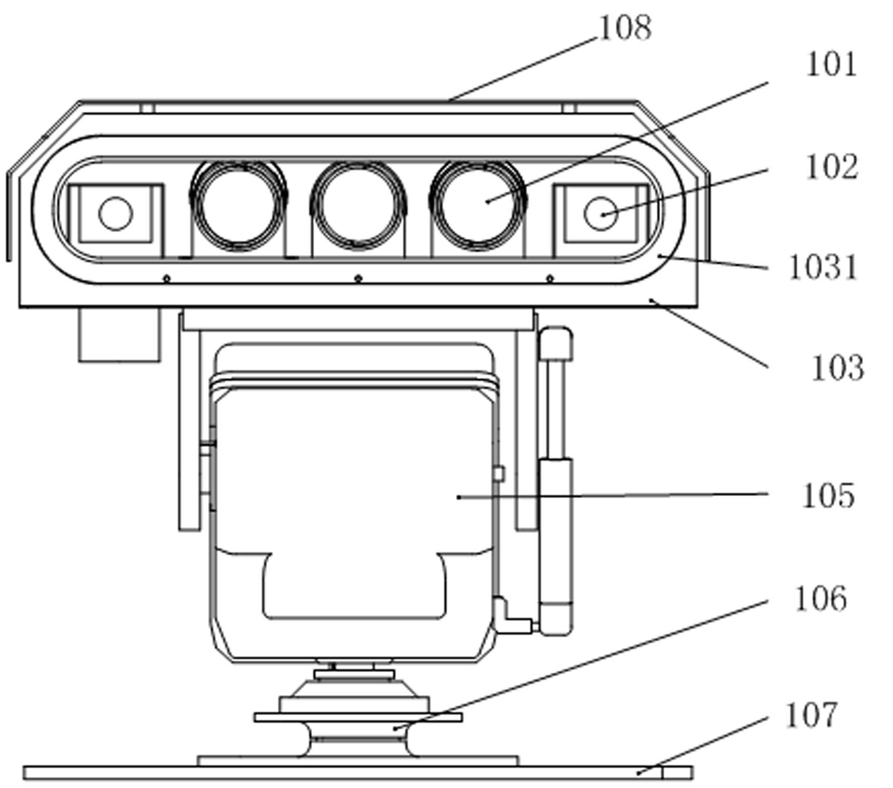
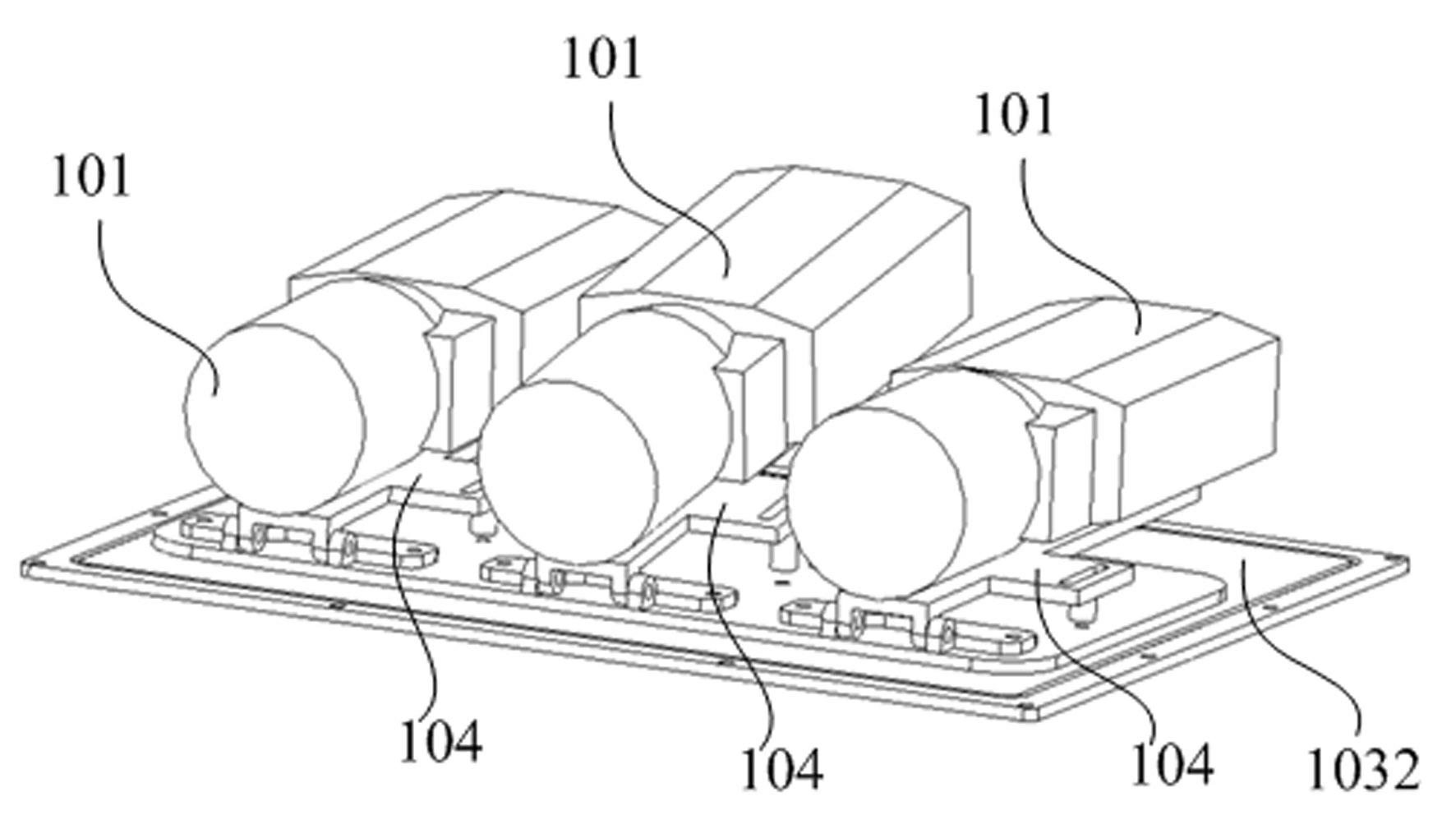
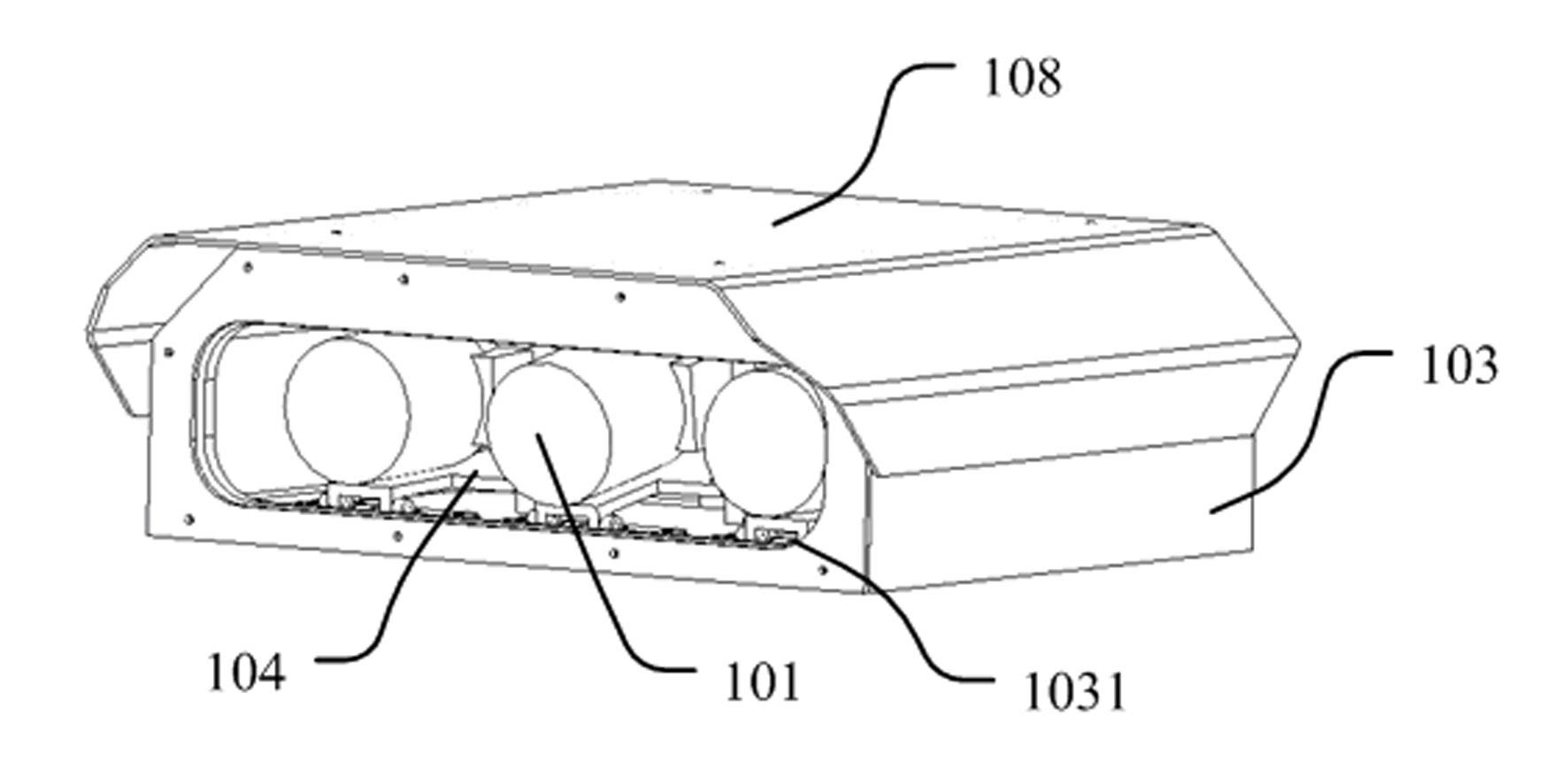
[0019] like Figure 1 to Figure 3 As shown, a foreign object scanning device on an airport road surface includes an imaging device 101, a near-infrared auxiliary lighting device, a protective cover 103, a rotation mechanism and a camera pitch adjustment mechanism 104, and the imaging device 101 includes three cameras and three lenses, Each camera is equipped with lenses of different focal lengths. The camera is a low-light camera, and the angle between the camera CCD target surface and the main optical axis is an acute angle. The lens is designed with near-infrared antireflection, and a 750nm~900nm Bandpass filter. The near-infrared auxiliary lighting equipment is two near-infrared laser light sources 102. The near-infrared auxiliary l...


PUM


Abstract

The invention relates to a device for scanning an airport pavement foreign object, which comprises an imaging device, near-infrared auxiliary lighting equipment, a protective cover, a rotating mechanism and a camera pitch adjusting mechanism. The protective cover is fixedly installed above the rotating mechanism; the protective cover is provided with a window; a base plate of the protective cover is provided with the camera pitch adjusting mechanism; the imaging device and the near-infrared auxiliary lighting equipment are arranged on the camera pitch adjusting mechanism, and installation positions of the imaging device and the near-infrared auxiliary lighting equipment correspond to a position of the window of the protective cover; and the imaging device and the near-infrared auxiliary lighting equipment are used for adjusting a scanning angle via the rotating mechanism and the camera pitch adjusting mechanism. By adopting the device for scanning the airport pavement foreign object, provided by the invention, the defects of the conventional airport pavement foreign object scanning equipment is used for detecting the minimum size of the foreign object to be detected slightly largely, is greatly affected by the rainy weather, the low illumination and the like, has a low detection function , is hard to operate at night and the like are solved; and the scanning device can operate day and night, and can be used for automatically detecting the small foreign object with size minimum to reach 5mm, and has high detection precision.

Description

technical field [0001] The invention relates to the technical field of foreign object monitoring on airport road surfaces, in particular to an airport road surface foreign object scanning device. Background technique [0002] FOD (Foreign Object Debris) is a foreign material, debris or object that may damage the aircraft or system. There are quite a few types of FOD, such as hard objects, soft objects, birds, lightning and so on. FOD hazards are very serious, foreign objects on the airport pavement can easily be sucked into the engine, resulting in engine failure. Debris can also accumulate in mechanical devices, affecting the proper operation of equipment such as landing gear and flaps. FOD not only damages the aircraft, causing an air crash that takes precious lives, but also entails huge economic losses. Unplanned engine replacements are expensive in and of themselves, not to mention the cost of delayed or cancelled flights. According to conservative estimates, the an...

Claims


Application Information

Patent Timeline
IPC IPC(8): H04N5/225G03B15/05G03B17/12G03B17/56F16M11/06F16M11/18F16M11/20
Inventor 马志明沈永宏艾莉刘彬袁红艳魏春景魏登武翁金明陆青平李伟温珂
Owner CHANGCHUN UP OPTOTECH
Why Eureka
Try Eureka