Surgical manipulator

A technique of surgical operations and manipulators, applied in surgery, small surgical forceps, medical science, etc., can solve problems such as accidental trauma or tearing of body parts

Inactive Publication Date: 2011-09-14
ASALUS MEDICAL INSTR
View PDF3 Cites 15 Cited by
  • Summary
  • Abstract
  • Description
  • Claims
  • Application Information

AI Technical Summary

Problems solved by technology

This can lead to accidental t

Method used


Image

  • Surgical manipulator
  • Surgical manipulator
  • Surgical manipulator

Examples


Embodiment Construction

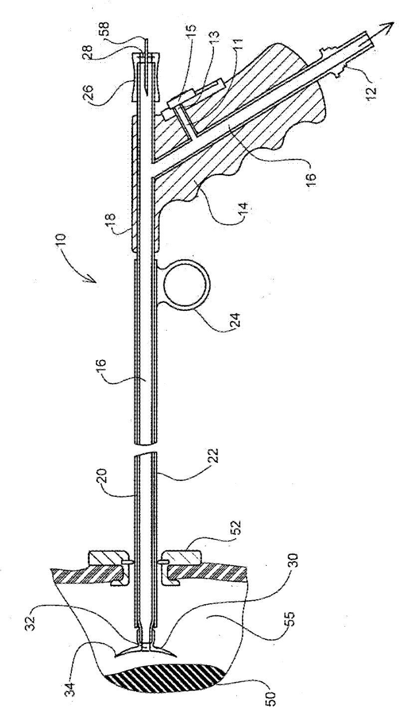
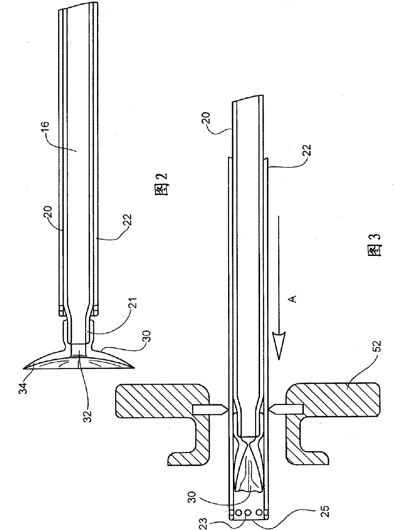
[0032] refer to figure 1 , the figure generally shows the surgical manipulator 10 . The manipulator 10 is used to manipulate the body part 50 in the patient's inflatable volume 55 . Manipulator 10 is generally introduced into body cavity 55 by means of introducer 22 (described in more detail below) through port 52 of a pre-inserted laparoscope. In use, the manipulator 10 is connected to a vacuum source at a connector 12 located at the base of a manipulator handle 14 . The handle 14 has a central channel 16 that extends from the connector 12 to a handle top 18 . Channel 16 extends from handle top 18 into extension 20 . At the distal end of the extension 20 there is a suction cup 30 including a central bore 32 in fluid communication with the channel 16 . Thus, suction is created at the suction cup when the connector 12 is connected to a vacuum source. This suction keeps the suction cup against the body part 50 and deformation of the generally circular flexible lip 34 of the...


PUM


Abstract

Surgical Manipulator A surgical manipulator (10) is disclosed which employs a suction cup (30) to hold body parts (50) whilst the manipulator is moved to manipulate the body part (50). Suction at the cup (30) is provided by means of a central passage (16) running through an extension (20) and through a handle part (14) to a vacuum connector (12). The suction at the cup (30) can be adjusted by a slider (15) which adjustably opens the passage (16) to atmosphere. Needles (58) and the like can be introduced into the passage (16) and thereby into the body part (50). For laparoscopic surgery the manipulator can be introduced into a laparoscopic port (52) by collapsing the suction cup (30) within an introducer sleeve (22 Fig 3). The introducer sleeve (22) can act as a suction device when the cup (30) is collapsed within it. The needle (58) can be replaced by a diathermy electrode (60 Fig 6) and irrigation is possible using an additional supply tube (121 Figure 4).

Description

technical field [0001] The present invention relates to a surgical manipulator, in particular but not exclusively, of the type used in laparoscopic or open surgery. Background technique [0002] Typically, manipulators used in laparoscopic surgery or other surgical procedures in which surgical instruments are operated remotely have some means of mechanically grasping tissue or body parts, such as jaws, fingers or hooks. These mechanisms are difficult to use, especially when remotely gripping or manipulating delicate body parts. [0003] Typically, laparoscopic surgical instruments must be inserted into small orifices formed in body cavities. Typically, these orifices are between 5mm and 12mm in diameter. When using mechanical manipulators, the jaws etc. are usually quite small so that they can be inserted through the aperture. Consequently, the surface area of ​​the mechanical manipulators at their grasping ends will be rather small, which causes considerable stress on th...

Claims


Application Information

Patent Timeline
IPC IPC(8): A61B17/34A61B17/02A61B17/30
CPCA61B2017/308A61B17/00234A61B2017/3488
Inventor N·沃伦
Owner ASALUS MEDICAL INSTR
Why Eureka
Try Eureka