Optical sensors for intraoperative procedures

a technology of optical sensors and intraoperative procedures, applied in the field of optical sensors, can solve the problems of affecting the oxygen circulation of the tissue, and complicating the procedure, and achieve the effect of reducing the pressure in the inflatable sleev

Active Publication Date: 2015-02-17
TYCO HEALTHCARE GRP LP
View PDF21 Cites 781 Cited by
  • Summary
  • Abstract
  • Description
  • Claims
  • Application Information

AI Technical Summary

Benefits of technology

[0011]In one embodiment, the intra-operative sensor device may be operatively coupled to a member which is adapted and configured to transition between a furled state and an unfurled state. In one embodiment, the member is an inflatable sleeve and a hose may be operatively coupled to the inflatable sleeve to provide inflation fluid. In the unfurled state, the inflatable sleeve may be inserted into an incision and placed adjacent a tissue. By reducing the pressure in the inflatable sleeve, the inflatable sleeve will transition to the furled state and may be wrapped around the adjacent tissue.

Problems solved by technology

For example, the presence of certain particulates or contaminants may complicate a procedure.
In addition, the lack of sufficient vascularization at the tissue site may disrupt adequate oxygen circulation to the tissue.
A lack of oxygen circulation to the tissue may endanger the function and survival of tissue.
The accuracy of the data collected, using such devices and methods, is limited by the configuration of the sensors used and the placement of the sensors in relation to the surgical site.
Disturbances, including a patient's motion and ambient lighting, may distort the measurements collected by the sensors.

Method used


Image

  • Optical sensors for intraoperative procedures
  • Optical sensors for intraoperative procedures
  • Optical sensors for intraoperative procedures

Examples


second embodiment

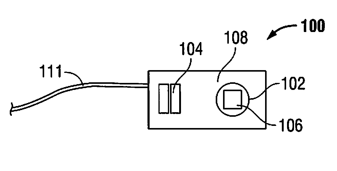
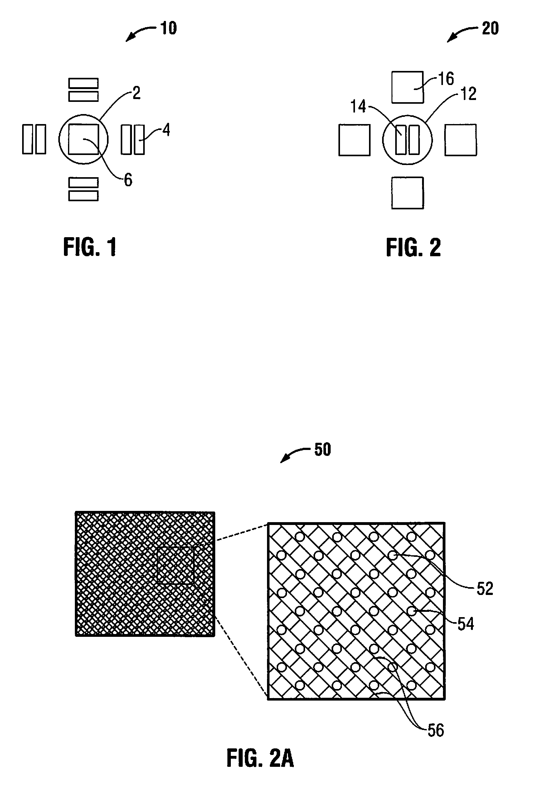
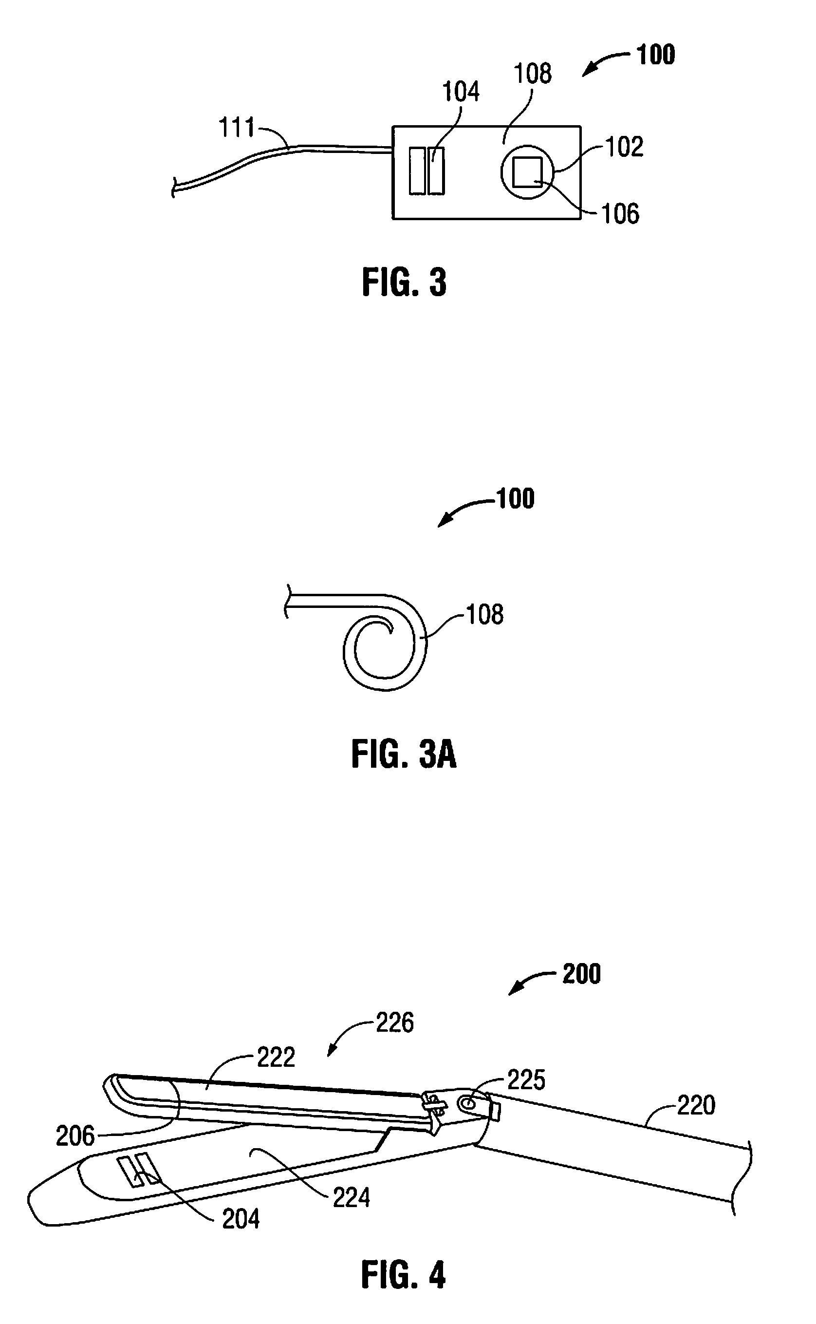
[0027]Depending upon the particular application, an intra-operative sensor may include a particular configuration of photo-detectors and light emitting sources. A first and an intra-operative sensor 10, 20 include different configurations of photo-detectors 6 and light emitting sources 4 and will now be described with reference to FIGS. 1 and 2.

first embodiment

[0028]an intra-operative sensor 10, as shown in FIG. 1, includes a photo-detector 6 around which multiple light emitting sources 4 are placed (more than one photo-detector could also be provided). The light emitting sources 4 may be placed radially around the one or more photo-detectors 6. In the embodiment shown, the light emitting sources 4 substantially encircle the photo detector(s) 6. In addition, the light emitting sources 4 may be spaced equidistantly apart from one another. Other spacings are also contemplated. The light emitting sources 4 may include, but are not limited to, light emitting diodes (LED's).

[0029]An optical isolator ring 2 may be placed around the one or more photo-detectors 6. In this manner, the ring 2 is between the detector(s) 6 and light emitting sources 4. The optical isolator ring 2 inhibits direct interference from light emitting sources or from ambient light, i.e., the ambient light of the operating room. By reducing the interference from light source...


PUM


Abstract

An intra-operative sensor device for detecting tissue or body parameters includes one or more light emitting sources and one or more photo-detectors. An optical isolator ring may be placed around either the one or more light emitting sources or around the one or more photo-detectors. The intra-operative sensor device may be a stand alone device or may be operatively coupled into a surgical instrument, such as a laparoscopic device.

Description

[0001]This application claims priority from provisional application Ser. No. 61 / 345,414, filed May 17, 2010, the entire contents of which are incorporated herein by reference.BACKGROUND[0002]1. Technical Field[0003]The present disclosure relates to devices and methods of using devices to monitor conditions within a body cavity, and more particularly to optical sensors and methods of using optical sensors during a surgical procedure to monitor the physical condition of the surgical site.[0004]2. Background of Related Art[0005]During or after a surgical procedure, the physical conditions of the surgical site might need to be monitored. The early detection of complications during or after a surgical procedure may facilitate a timely therapeutic response prior to the onset of irreversible damage. For example, the presence of certain particulates or contaminants may complicate a procedure. In addition, the lack of sufficient vascularization at the tissue site may disrupt adequate oxygen ...

Claims


Application Information

Patent Timeline
Patent Type & Authority Patents(United States)
IPC IPC(8): A61B5/1455A61B5/00A61B17/00A61B17/072A61B17/115A61B17/29A61B19/00
CPCA61B5/0059A61B5/14552A61B5/0084A61B5/6833A61B5/6846A61B5/6876A61B5/6884A61B19/46A61B17/07207A61B17/1155A61B17/29A61B2017/00057A61B2017/00544A61B2017/2927A61B2019/521A61B2562/164A61B2090/309A61B90/06
Inventor BANERJEE, SAUMYASTOPEK, JOSHUA BENJAMINSARGEANT, TIMOTHY
Owner TYCO HEALTHCARE GRP LP
Why Eureka
Try Eureka