
Surgical stapling and cutting apparatus—deployment mechanisms, systems and methods

a technology of surgical stapling and cutting apparatus, applied in the field of medical devices, can solve the problems of complex suturing procedures that are time-consuming and/or difficult to effectively perform, suturing may be impractical or inability to be carried out in certain situations, and requires significant skill to perform suturing

Active Publication Date: 2017-06-27
TOUCHSTONE INTERNATIONAL MEDICAL SCIENCE CO LTD
View PDF7 Cites 819 Cited by
  • Summary
  • Abstract
  • Description
  • Claims
  • Application Information

AI Technical Summary

Benefits of technology

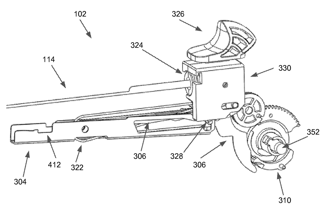
[0009]A surgical stapling device comprises a mode switch member to select a drive assembly to a deployment mode and a trigger member to activate the drive assembly to advance a deployment assembly to staple and cut a target tissue. The surgical stapling device further includes a deployment slide member to advance the deployment assembly in a first direction to drive both a wedge assembly to deploy staples into the target tissue and a knife member to cut the target tissue. The surgical device also includes a reset switch member to place a swing arm member with a reset tab element in a first reset position to release a clamp lock member to unclamp a jaw assembly to release the target tissue and to further place the swing arm member in a second reset position without causing displacement of the deployment assembly to release a deployment reset member.
[0010]A surgical stapling device comprises a mode switch member to select drive assembly to a deployment mode and a trigger member to activate the drive assembly to advance a deployment assembly to staple a target tissue. The surgical stapling device also includes a deployment slide member to advance the deployment assembly in a first direction to drive a wedge assembly to deploy staples into the target tissue and a reset switch member to place a swing arm member with a reset tab element in a first reset position to release a clamp lock member to unclamp a jaw assembly to release the target tissue and to further place the swing arm member in a second reset position without causing displacement of the deployment assembly to release a deployment to release a deployment reset member.

Problems solved by technology

However, proper suturing requires significant skills to perform; in particular, complex suturing procedures can be time-consuming and / or very difficult to perform effectively.
Furthermore, suturing may be impractical or unfeasible in certain situations.
For example, suturing may be very difficult to perform in minimally-invasive surgical procedures where suturing tools may be required to be inserted through a small opening (often referred to as an access port) to gain access into a patient's body, and then the suturing operation is performed through the small access opening with extension tools to suture the target tissue.
In such minimally-invasive surgical procedures, the opening or access port to the surgical site inside the patient may not be large enough to allow effective maneuvering of suturing tools to perform the suturing procedure efficiently and effectively.
Indeed, as surgical technology continues to progress, the size of the access ports required to access surgical sites in the body to perform minimally-invasive procedures correspondingly continues to decrease.
When instruments of such small diameters are used, the size of the access ports may also be very small.
However, because of restricted access, it can be significantly difficult or nearly impossible sometimes to perform effective manual suturing within a patient's body through these small access ports in minimally-invasive procedures.

Method used


Image

  • Surgical stapling and cutting apparatus—deployment mechanisms, systems and methods
  • Surgical stapling and cutting apparatus—deployment mechanisms, systems and methods
  • Surgical stapling and cutting apparatus—deployment mechanisms, systems and methods

Examples


Embodiment Construction

[0023]In the following detailed description, specific details are set forth in order to provide a thorough understanding of the present invention. However, it will be readily understood by those skilled in the art that the present invention may be practiced without these specific details. Alternatively, some of the well-known parts, component, hardware, methods of operations, and procedures may not be described in detail or elaborated so as to avoid obscuring the present invention; but, nevertheless, they are within the spirit and scope of the present invention.

[0024]As mentioned, surgeons use sutures to close wounds and incisions, attach separate tissue structures to one another, and perform other medical or surgical functions in various surgical procedures or operations. However, proper suturing requires significant skills to perform; in particular, complex suturing procedures can be time-consuming and / or very difficult to perform effectively. Furthermore, suturing may be impracti...


PUM


Abstract

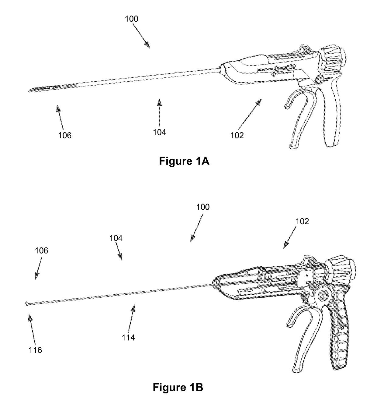
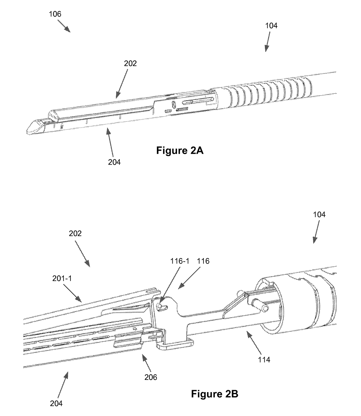
A surgical stapling device is configured for use in open and / or laparoscopic surgical procedures. The device includes a handle assembly, a shaft assembly coupled to the handle assembly, and an end-effector coupled to the shaft assembly. The end-effector comprises of a jaw assembly configured to clamp, staple, and / or cut a target tissue. The handle assembly comprises of a trigger element that can activate a drive assembly to advance a deployment assembly to staple and / or cut the aforementioned target tissue. The deployment assembly comprises of a deployment slide member to either advance the deployment assembly in a first direction or retreat the deployment assembly in a second direction.

Description

CROSS-REFERENCE TO RELATED APPLICATION(S)[0001]The application claims priority to Provisional U.S. Patent Application No. 61 / 821,493, filed on May 9, 2013, which is incorporated herein by reference.FIELD OF THE INVENTION[0002]The present invention relates generally to medical devices, and more particularly to surgical stapling and cutting systems, such as endocutters and microcutters.BACKGROUND[0003]Traditionally, surgeons use sutures to close wounds and incisions, attach separate tissue structures to one another, and perform other medical or surgical functions in various surgical procedures or operations. However, proper suturing requires significant skills to perform; in particular, complex suturing procedures can be time-consuming and / or very difficult to perform effectively. Furthermore, suturing may be impractical or unfeasible in certain situations. For example, suturing may be very difficult to perform in minimally-invasive surgical procedures where suturing tools may be requ...

Claims


Application Information

Patent Timeline
Patent Type & Authority Patents(United States)
IPC IPC(8): A61B17/068A61B17/072A61B17/064A61B17/00A61B17/29
CPCA61B17/068A61B17/07207A61B2017/00389A61B2017/0647A61B2017/2902A61B2017/294A61B2017/2923A61B2017/2946
Inventor FERNANDEZ, ANTHONY J.KNODEL, BRYAN D.
Owner TOUCHSTONE INTERNATIONAL MEDICAL SCIENCE CO LTD
Learn More