Rolling bearing and rotating shaft support structure

A technology for rolling bearings and rotating shafts, applied to rolling contact bearings, roller bearings, bearings for rotational motion, etc., can solve problems such as inability to reduce noise, vibration, and damage to oil seals, and achieve good packaging and productivity , Noise reduction, good productivity and fitability

Inactive Publication Date: 2016-02-03
NTN CORP
View PDF6 Cites 0 Cited by
  • Summary
  • Abstract
  • Description
  • Claims
  • Application Information

AI Technical Summary

Problems solved by technology

However, oil seals may be damaged due to prolonged exposure to high temperature engine oil
In this way, noise, vibration and

Method used


Image

  • Rolling bearing and rotating shaft support structure
  • Rolling bearing and rotating shaft support structure
  • Rolling bearing and rotating shaft support structure

Examples


Embodiment Construction

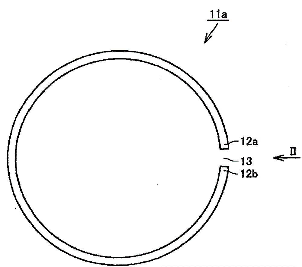
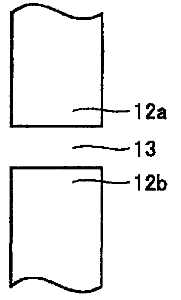
[0049] Hereinafter, embodiments of the present invention will be described with reference to the drawings. figure 1 It is a figure which shows the resin retaining ring with which the rolling bearing which concerns on one Embodiment of this invention is equipped. figure 2 From figure 1 Observed in the direction indicated by the arrow II in the figure 1 An enlarged view of a portion of the resin retaining ring shown. It should be noted, figure 1 This corresponds to a view viewed from the axial direction, that is, from the direction of the rotation axis of the rolling bearing when it is arranged in a rolling bearing described later.

[0050] refer to figure 1 and figure 2 The resin retaining ring 11 a is made of resin, and has a shape obtained by cutting a part of the annular member in the circumferential direction in order to form the gap 13 . That is, the resin retaining ring 11a has two end portions 12a, 12b opposed in the circumferential direction, and has a stru...


PUM


Abstract

A rolling bearing (21) comprises: an outer ring formed by circumferentially arranging divided outer ring parts (25a, 25b); rollers (23) rolling on the raceway surface of the outer ring; and a resin retainer (11a) formed by cutting an annular member at one point in the circumferential direction of the member, disposed on the outer-diameter side of the outer ring so as to be in contact with the outer ring, and restraining radial movement of the divided outer ring parts (25a, 25b).

Description

technical field [0001] The invention relates to a rolling bearing and a rotating shaft support structure, in particular to a rolling bearing and a rotating shaft supporting structure used in an environment with large temperature changes. Background technique [0002] Needle roller bearings composed of an outer ring, needle rollers, and cages have a small bearing projected area, but they can withstand high loads and have high rigidity. Therefore, taking advantage of such characteristics, it is effectively utilized as a bearing for supporting automotive components, especially a crankshaft of an automotive engine. Bearings for motor vehicle engines are used in a wide range of temperature environments from cooling around -30°C to driving around 150°C. [0003] When installing the needle roller bearing for supporting the crankshaft into the crankshaft, it is difficult to install it from the axial direction because the balance weight and the like interfere with the needle roller ...

Claims


Application Information

Patent Timeline
Patent Type & Authority Patents(China)
IPC IPC(8): F16C35/077F16C19/36F16C33/60F16C43/04
CPCF16C33/60F16C19/466F16C35/077F16C43/04
Inventor 片山昭彦
Owner NTN CORP
Why Eureka
Try Eureka