Device for bending optical fiber and receiving light

一种受光器、光纤的技术,应用在光纤弯曲受光器领域,能够解决偏差、泄漏光耦合等问题

Active Publication Date: 2011-09-14
FUJIKURA LTD
View PDF8 Cites 3 Cited by
  • Summary
  • Abstract
  • Description
  • Claims
  • Application Information

AI Technical Summary

Problems solved by technology

Therefore, when the narrow-diameter optical fiber 142 is held between the concave surface 111 of the concave holding member 110 and the convex surface 121 of the convex holding member 120, as Figure 20 As shown, the optical fiber bending optical receiver 101 cannot be in the width direction of the convex surface 121 ( Figure 20 up and down on the paper) to fix the position of the thin-diameter optical fiber 142
As a result, there is the following unfavorable situation: the optical fiber 142 may be greatly displaced from the light receiving surface 131 of the light receiving element 130, and only a part of the leaked light is coupled, and the measurement of the leaked light may deviate.

Method used


Image

  • Device for bending optical fiber and receiving light
  • Device for bending optical fiber and receiving light
  • Device for bending optical fiber and receiving light

Examples


Deformed example 1

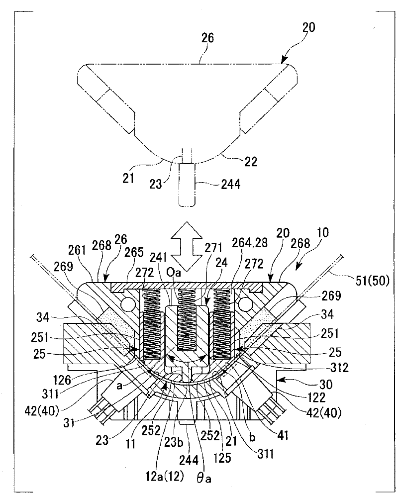
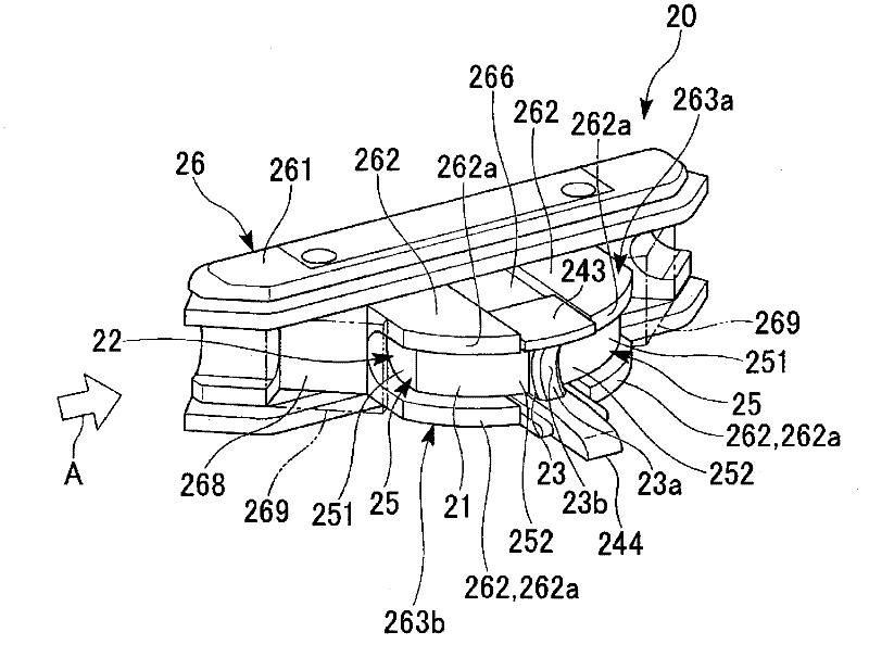
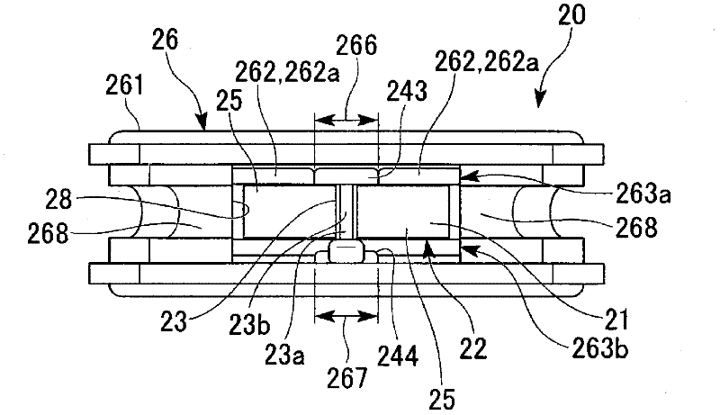
[0149] In the above-mentioned embodiment, the configuration in which the alignment recessed portion 23 a for the optical fiber is provided only at the front end portion of the convex portion 22 of the convex holding member 20 was exemplified. However, as the convex part of the convex grip member of the present invention, it is not limited to such a structure, and the positioning protrusions 23 of the convex part 22 of the convex grip member 20 described above may also be placed between the convex surfaces on both sides. A part or the whole is made into the concave surface which forms the recessed part for position alignment of an optical fiber.

[0150] Figure 15 It means that the positioning protrusions 23 of the convex part 22 of the above-mentioned convex holding member 20 are changed from both ends in the width direction to the central part within the entire length of the convex surface on both sides. The convex portion 22A is formed of a concave groove-shaped convex sur...

Deformed example 2

[0153] In the above-mentioned embodiment, as the convex portion 22 of the convex holding member 20, a convex portion composed of three movable members 24, 25, 25 that can be collapsed is illustrated, but it is also possible to use only one of the convex portions. One part is used as the collapsible part and the other part is used as the fixed part in the male gripping member (that is, in the male gripping member, it is fixed to the male gripping member main body in which the collapsible part is incorporated).

[0154] Figure 16 It is exemplified that a movable member 24A (a collapsible part) with a positioning protrusion 23 protrudingly provided as a protrusion, and a protruding wall fixed to a convex holding member main body 26A and provided on both sides of the movable member 24A are used. The convex holding member 20A of the convex portion 22B constituted by the side fixing walls 25A, 25A.

[0155] The above-mentioned convex holding member main body 26A is, specifically, ...


PUM


Abstract

A device for bending an optical fiber and receiving light is provided with a recessed holding member having a recess, a projecting holding member having a projection projecting toward the recess, light receiving elements for receiving leak light from the optical fiber held between the recess and the projection, and a supplemental support mechanism substantially independent of the recess or the projection and supplementarily supporting the optical fiber between the recess and the projection so that the leak light from the optical fiber is received by the centers of the light receiving elements.

Description

technical field [0001] The present invention relates to an optical fiber bending photoreceiver used as an optical fiber core wire comparator, a live wire detector, and the like. The optical fiber bending receiver is used in optical fiber projects such as laying, maintenance and dismantling of optical fibers. In particular, it relates to an optical fiber bending photoreceiver for non-destructively performing a core wire comparison inspection of an optical fiber, such as an optical fiber core wire, an optical fiber fiber wire, and an optical fiber cord, and live wire discrimination. [0002] this application claims priority based on Japanese Patent Application No. 2008-293641 for which it applied to Japan on November 17, 2008, and uses the content here. Background technique [0003] Such an optical fiber bending receiver includes a mechanism (fiber gripping and bending imparting mechanism) for gripping and bending an optical fiber such as an optical fiber core, an optical fib...

Claims


Application Information

Patent Timeline
Patent Type & Authority Applications(China)
IPC IPC(8): G01M11/00G02B6/00G02B6/42
CPCG02B6/2852G01M11/088G02B6/4201G02B6/4289
Inventor 新见慎一川西纪行
Owner FUJIKURA LTD
Why Eureka
Try Eureka