Liquid densitometer

一种浓度计、液体的技术,应用在悬浮液和多孔材料分析、仪器、分析材料等方向,能够解决测定误差、不能避免测定误差、原材料污染配管电阻等问题,达到误差稳定、误差小、稳定测定的效果

Inactive Publication Date: 2011-08-17
KURASHIKI BOSEKI KK
View PDF6 Cites 4 Cited by
  • Summary
  • Abstract
  • Description
  • Claims
  • Application Information

AI Technical Summary

Problems solved by technology

[0006] 1) Measurement errors due to fouling of containers or tubes,
[0007] 2) Measurement error due to air bubbles in the container or tube,
[0008] 3) Measurement errors due to changes in the shape of the tube
[0010] However, it is not completely effective for any form of the liquid concentration meter disclosed in Patent Document 1, and measurement errors due to bubble adhesion cannot be avoided.
In addition, since the installation of spherical bodies or resistance parts in the container will cause contamination from the material or increase the resistance of the piping, it is contrary to the improvement of the quality of the piping.

Method used


Image

  • Liquid densitometer
  • Liquid densitometer
  • Liquid densitometer

Examples


Embodiment Construction

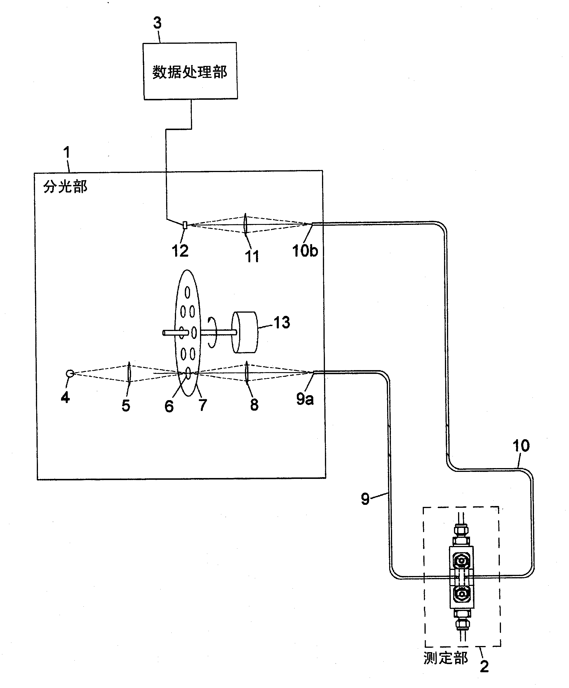
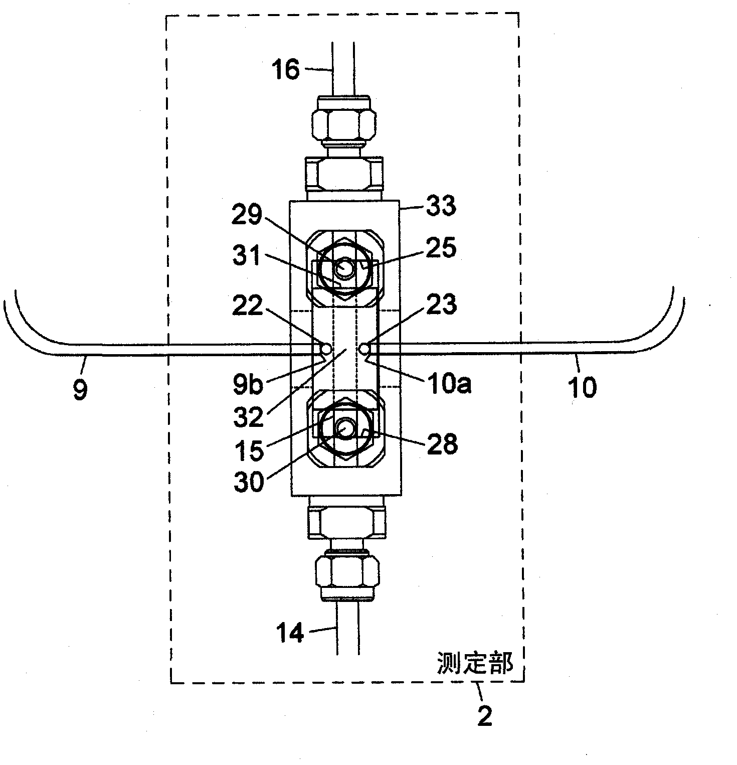
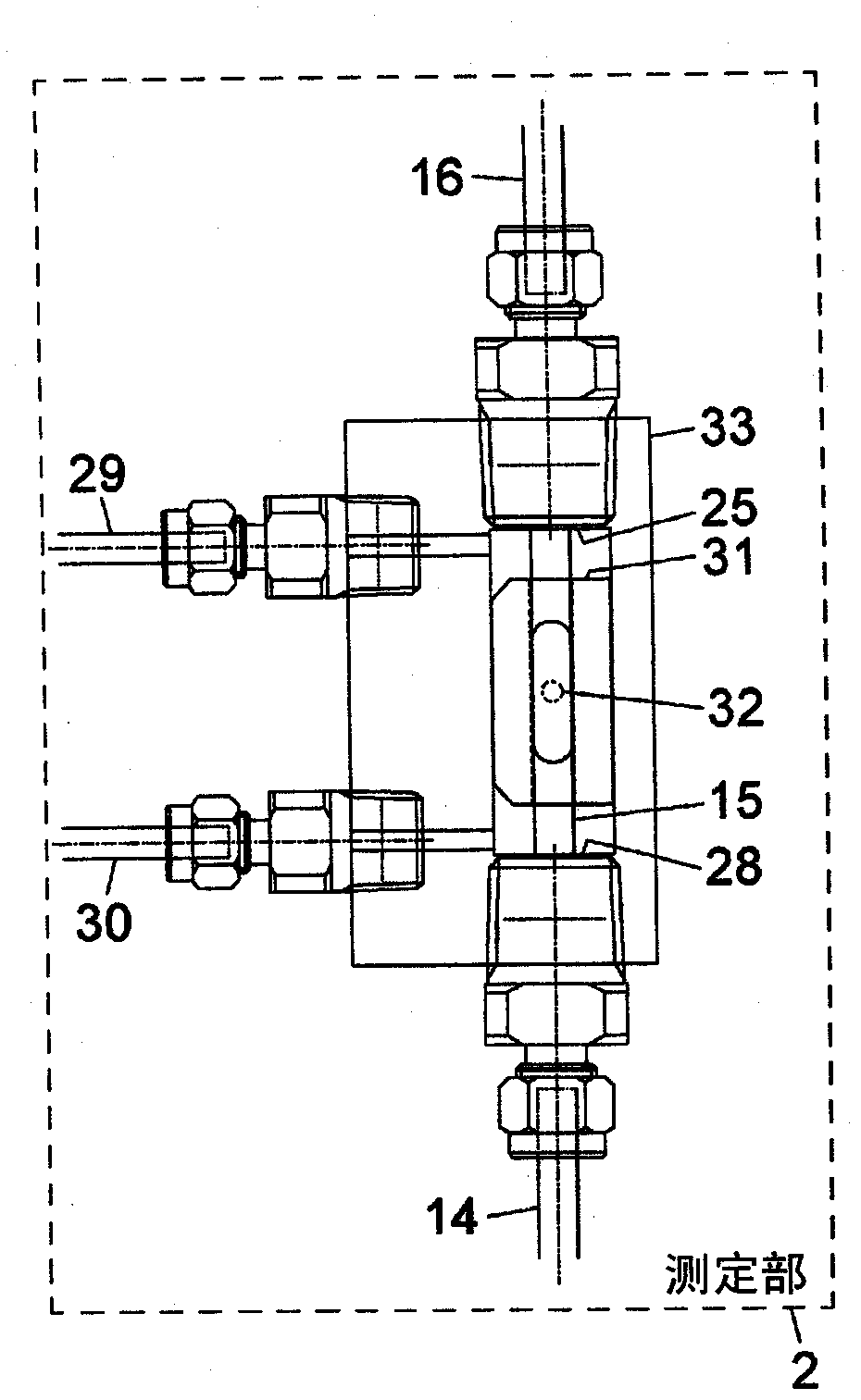
[0050] figure 1 It is a figure which briefly shows an Example. figure 2 , image 3 It is a figure which shows the measurement part of this Example. figure 2 is a plan view of the measurement unit, image 3 It is a side view of the measurement unit. Figure 4 and Figure 5 It is a cross-sectional view for explaining the operation of the measurement unit of this embodiment.

[0051] Such as figure 1 As shown, the liquid concentration meter is substantially composed of a spectroscopic part 1 , a measuring part 2 , and a data processing part 3 .

[0052] First, a specific configuration of the spectroscopic unit 1 will be described.

[0053] The spectroscopic unit 1 is provided with a tungsten lamp 4 as a light source, a convex lens 5 , a rotating disc 7 including eight interference filters 6 , a convex lens 8 , a convex lens 11 , and a light receiving element 12 . The light emitted by the tungsten filament lamp 4 is collected by the convex lens 5 and passes through the i...


PUM


Abstract

A liquid density in a liquid supply tube, through which the liquid is supplied, is stably measured from the outside of the liquid supply tube. A liquid densitometer is provided with a liquid supply tube (14, 16) through which a liquid is supplied, a light transmission unit (15) set at a halfway point of the liquid supply tube (14, 16), a light projection unit (9, 22) that irradiates measurement light to the light transmission unit (15), a light reception unit (10, 23) that receives the measurement light to transmit through the light transmission unit (15), a support member (31) that supports movably the light projection unit (9, 22) and the light reception unit (10, 23) so as to move a measurement position (32) from which the light is irradiated to the light transmission unit (15) and at which the light reception unit (10, 23); receives the light transmitting through the light transmission unit (15), a measurement position moving mechanism (2) that makes the support member (31) move in order for the measurement position (32) to move in a predetermined area of the light transmission unit (15), and a data processing unit that acquires light intensity data which the light reception unit (10, 23) receives at a plurality of measurement positions (32) to calculate a density of the liquid, which flows through the liquid supply tube (14, 16), in accordance with the plurality of the light receiving intensities.

Description

technical field [0001] The present invention relates to a liquid concentration meter, in particular to a liquid concentration meter comprising a projection unit, a light receiving unit, and a data processing unit, wherein the projection unit is used to irradiate light to a light-transmitting unit provided in a liquid delivery pipe for transporting liquid, The light receiving part is used to receive the light passing through the light transmitting part, and the data processing part calculates the concentration of the liquid according to the intensity of the light received by the light receiving part. Background technique [0002] As a technique for measuring the liquid concentration in a tube that transports liquid, a liquid concentration meter that optically measures the liquid concentration is known (for example, refer to Patent Documents 1 and 2). In such a liquid concentration meter, since there is a problem of changing the shape of the tube when directly measuring the li...

Claims


Application Information

Patent Timeline
Patent Type & Authority Applications(China)
IPC IPC(8): G01N21/01G01N21/15G01N21/27G01N21/59
CPCG01N2021/152G01N21/5907G01N21/15G01N2201/0639G01N15/06G01N21/27G01N21/59G01N21/03G01N21/05G01N21/1702G01N21/8507
Inventor 横田博平木哲安田信义
Owner KURASHIKI BOSEKI KK
Why Eureka
Try Eureka