Wiring configuration for throttle body in small vehicle

A wiring structure and throttle technology, applied in combustion air/combustion-air handling, internal combustion piston engine, engine components, etc., can solve problems such as the need for space, reduce processing space, suppress processing space, eliminate body width and The effect of seat height restrictions

Active Publication Date: 2014-01-29
HONDA MOTOR CO LTD
View PDF5 Cites 0 Cited by
  • Summary
  • Abstract
  • Description
  • Claims
  • Application Information

AI Technical Summary

Problems solved by technology

[0005] However, in the case shown in the above-mentioned Patent Document 1, a wide wiring extends from the throttle valve area in the vehicle width direction, and in order to cope with the oscillation of the power unit relative to the vehicle, space is required for handling the wiring.

Method used


Image

  • Wiring configuration for throttle body in small vehicle
  • Wiring configuration for throttle body in small vehicle
  • Wiring configuration for throttle body in small vehicle

Examples


Embodiment Construction

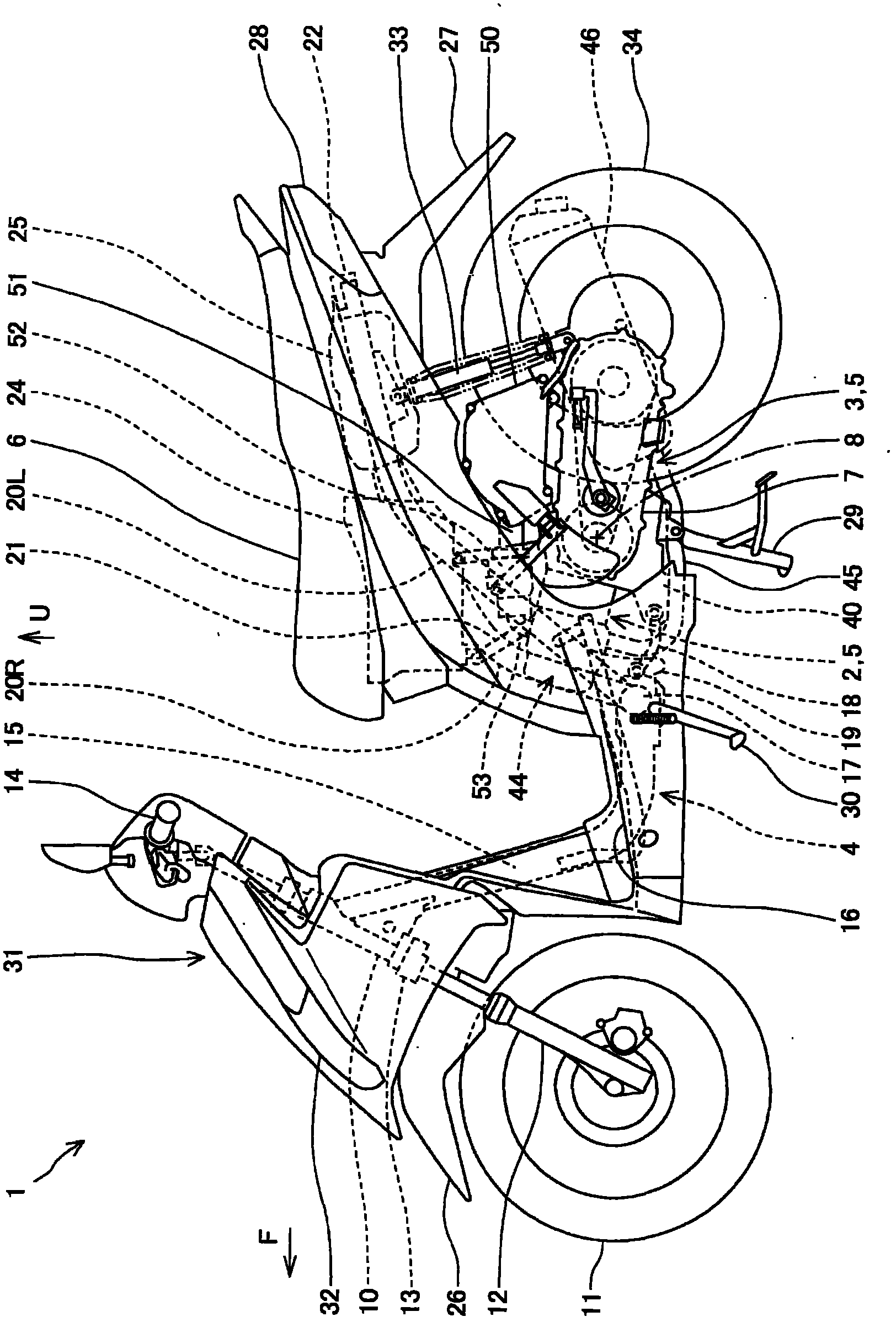
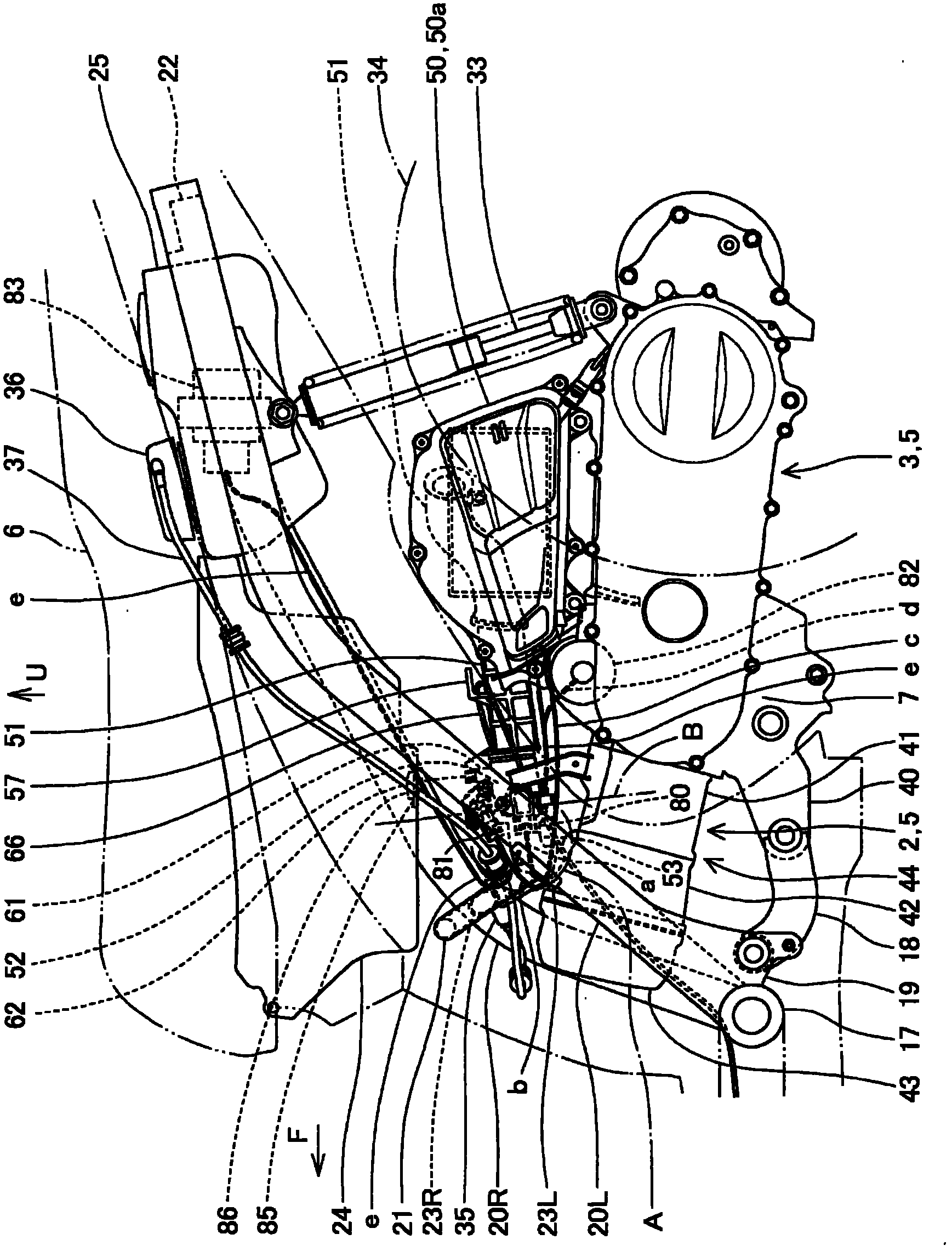
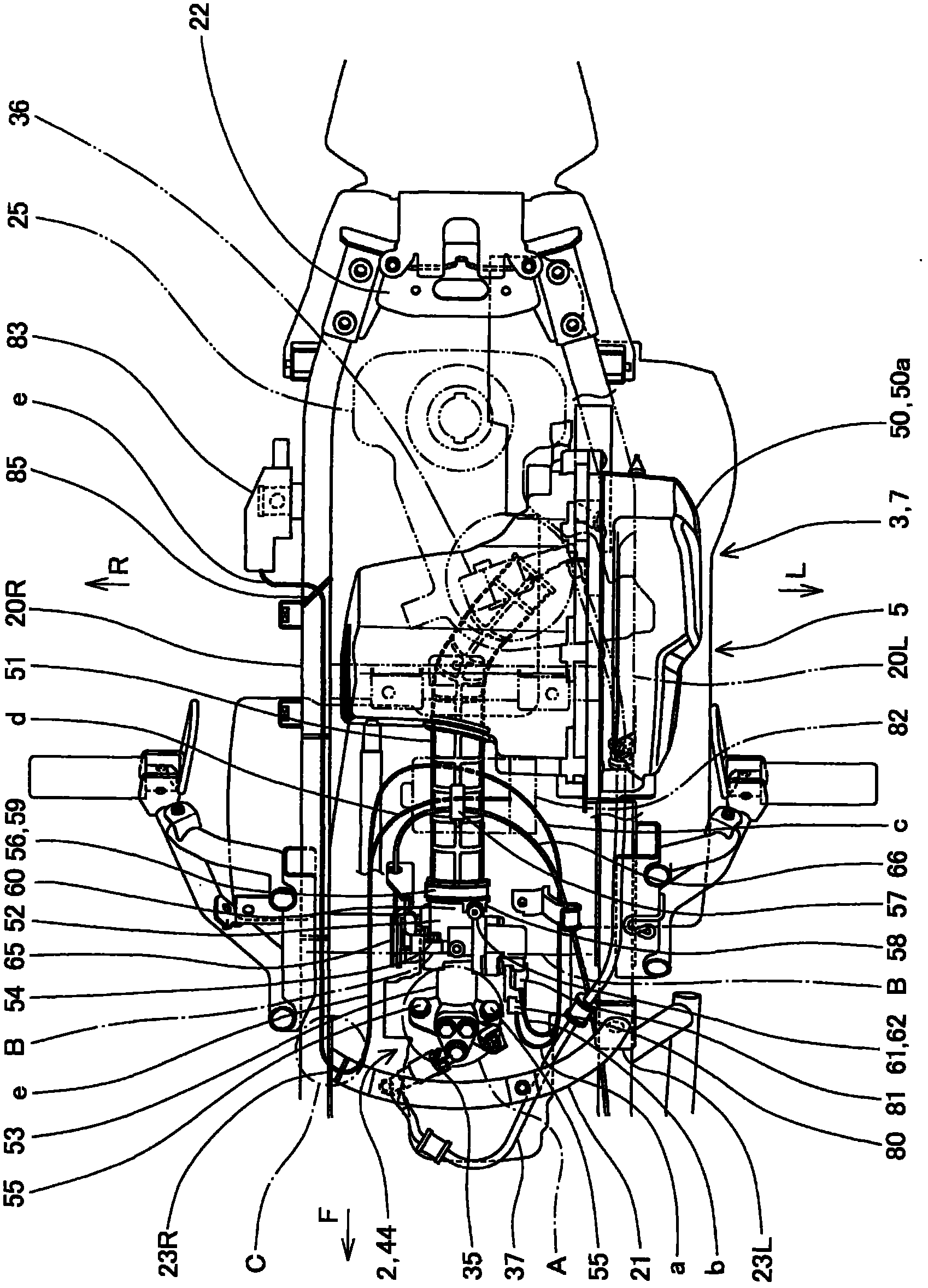
[0081] Below, refer to Figure 1 to Figure 9 , the wiring structure to the throttle region of the small vehicle according to the embodiment of the present invention will be described.

[0082] It should be noted that directions such as front, rear, left, right, up and down in the description of this specification and the claims refer to the directions of a vehicle in which the power unit according to this embodiment is mounted on a vehicle, particularly a small vehicle such as a motorcycle. direction. In the figure, arrow F indicates the front of the vehicle, L indicates the left side of the vehicle, R indicates the right side of the vehicle, and U indicates the upper side of the vehicle.

[0083] In addition, in the drawings, hollow arrows schematically indicate the flow of intake air to the internal combustion engine, small arrows m schematically indicate the flow of idle air, and small arrows n schematically indicate the flow of bypass air at startup.

[0084] figure 1 ...


PUM


Abstract

In a small vehicle (1) provided with a power unit (5) including an internal combustion engine 2 and a power transmission system (3) and swingably attached to a body frame (4) below a seat (6), the wiring configuration for the throttle body in the small vehicle (1) includes a throttle body (52) disposed between the power unit and seat, an opening sensor (68) for detecting the degree of throttle opening, provided at an end of a throttle valve shaft (64) aligned along the width direction of the vehicle, an actuator (70) for controlling the throttle body, attached to the throttle body in the vicinity of the opening sensor, and a first wiring coupler (80) of the opening sensor and a second wiring coupler (81) of the actuator, the first and second wiring couplers (80, 81) being separately attached in the same front / rear direction so as to intersect with respect to the throttle valve shaft.

Description

technical field [0001] The present invention relates to a wiring structure to a throttle valve area of ​​a small vehicle that swingably supports a power unit. Background technique [0002] In the past, the wiring to the throttle area of ​​a small vehicle with a power unit swinging support has adopted the following structure: a control unit that integrates multiple functions of an actuator and a sensor is integrally installed in the throttle area, and a single wiring coupler is used. (Japanese: wiring カプラ) to connect with the outside. [0003] For example, as shown in the following patent document 1, a single wiring coupler facing the vehicle width direction in a manner perpendicular to the intake passage of the throttle section is provided on the upper part of the throttle section, and an external wiring coupler is connected to the single wiring coupler. coupler. [0004] Patent Document 1: Japanese Patent No. 3975065 ( image 3 , 4 、5) [0005] However, in the case show...

Claims


Application Information

Patent Timeline
Patent Type & Authority Patents(China)
IPC IPC(8): F02D9/10
CPCF02D9/105F02M35/162F02D2011/102F02D9/1055F02D2400/22F02D11/106Y02T10/14F02D2009/0252F02D2009/0294F02M35/10039Y02T10/12
Inventor 池田健一郎洼田俊行
Owner HONDA MOTOR CO LTD
Why Eureka
Try Eureka