Connector and connector matching method

A connector and mating state technology, which is applied in the direction of connection, parts of the connecting device, coupling device, etc., can solve the problems of damaging the reliability of the connector mating, dust sticking to the mating surface, etc.

Inactive Publication Date: 2011-09-21
SUMITOMO WIRING SYST LTD
View PDF8 Cites 3 Cited by
  • Summary
  • Abstract
  • Description
  • Claims
  • Application Information

AI Technical Summary

Problems solved by technology

However, once the mated state is released, the mating surfaces of the first housing and the second housing are exposed to the external environment, so there is a concern that foreign matter such as dust sticks to the mating surfaces

Method used


Image

  • Connector and connector matching method
  • Connector and connector matching method
  • Connector and connector matching method

Examples


Embodiment Construction

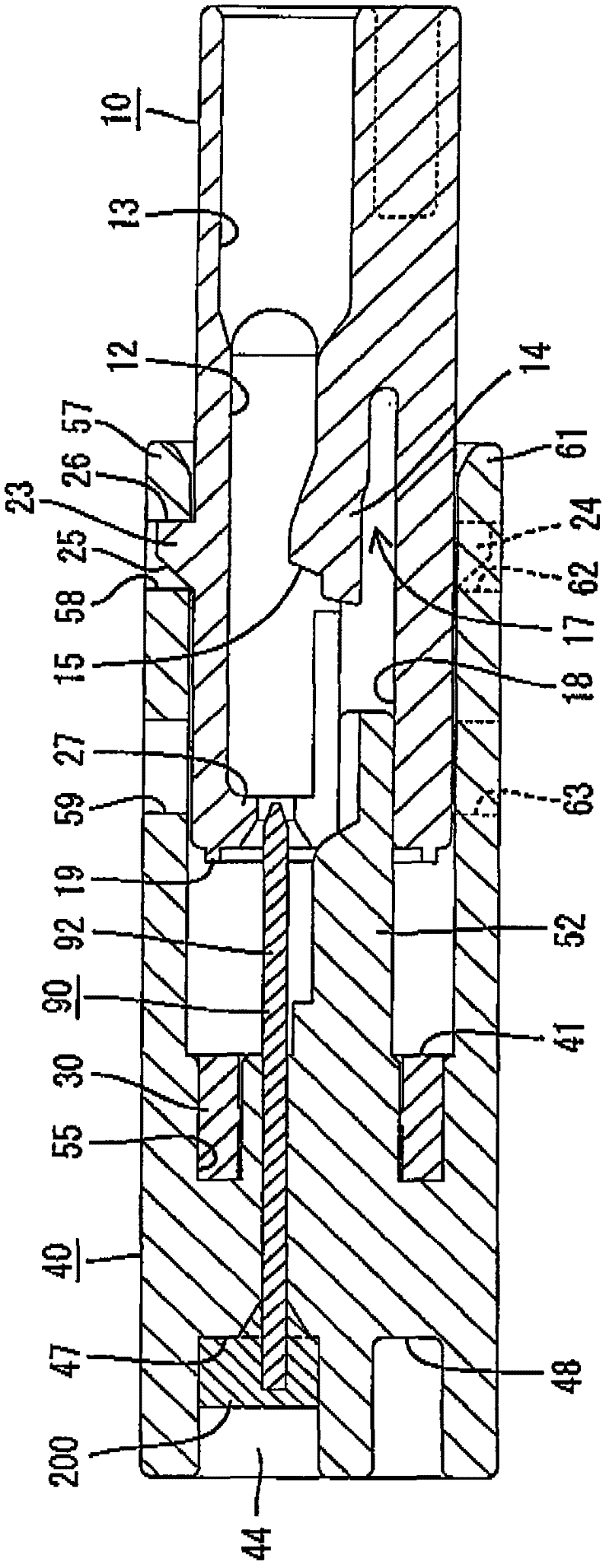
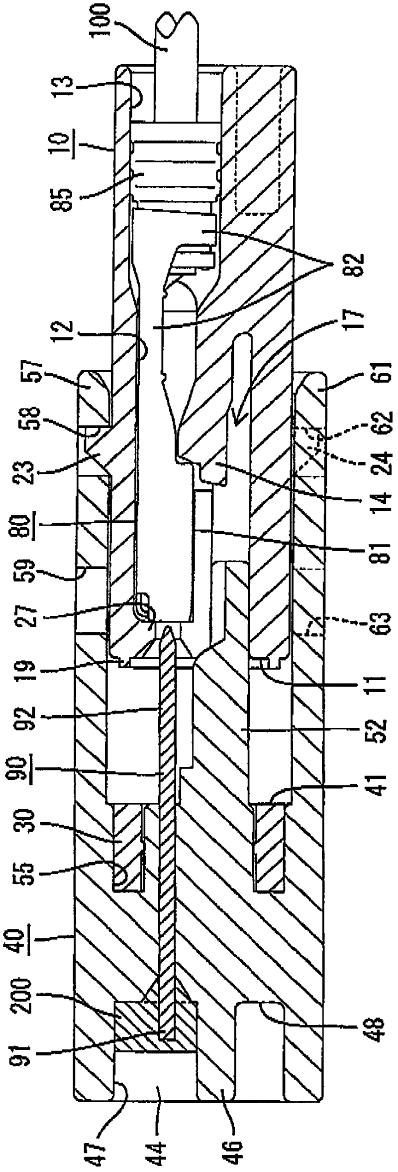
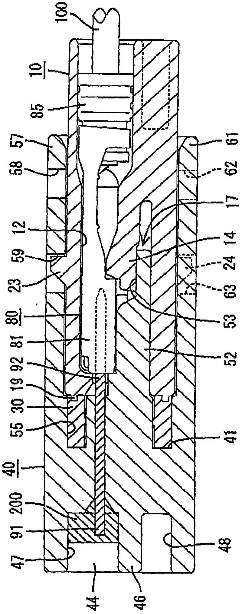
[0059] In the following, reference will be made to Figure 1 to Figure 9 Example 1 of the present invention will be described. The connector according to Embodiment 1 is equipped with a first housing 10 and a second housing 40 capable of fitting with each other. The first terminal fitting 80 and the second terminal fitting 90 are fitted to the first housing 10 and the second housing 40, respectively. The second terminal fitting 90 is configured as a fitting terminal not connected to an electric wire. In the following description, the respective mating surface sides (opposing surfaces 11 , 41 ) of the first housing 10 and the second housing 40 are set to the front side in the longitudinal direction.

[0060] The first housing 10 is formed of synthetic resin, and has a flat block shape, such as figure 1 with Figure 8 shown. A plurality of cavities 12 are formed in the first housing 10 to be aligned in the width direction. Rubber plug insertion ports 13 , into which rubber...


PUM


Abstract

The present invention relates to a connector and a connector matching method. The connector comprises the following components: a first housing and a second housing which are matched with each other; a first terminal joint and a second terminal joint which are respectively mounted on the first housing and the second housing, wherein, the first housing and the second housing respectively comprise the following components: a part keeping unit which is constructed for keeping the two housings in a keeping state at a partial locking position, wherein the first terminal joint is assembled in the first housing at a manually hollow matching state; and a total keeping unit which is constructed for keeping the two housings at a total locking position, wherein when the two housings are moved from the partial locking position along a matching direction and are matched with each other at a normal depth, the first terminal joint and the second terminal joint are connected normally.

Description

technical field [0001] The invention relates to a connector and a connector mating method. Background technique [0002] A conventional connector is disclosed in JP-A-2008-21498. The connector is equipped with a first housing to which a female terminal with an electric wire is fitting-fitted, and a second housing to which the joint terminal is fitted. [0003] At the work site where the two housings are assembled together, first, the first terminal joint is fitted to the first housing, and then the position of the first housing is set in this state to face the second housing fitted with the joint terminal. Two housings, and then use one action to bring the two housings into the normal mating position. [0004] Thus, as described above, at the work site where the two housings are fitted together, the work of fitting the first terminal fittings to the first housing must be performed separately, so that the corresponding parts of the first housing and the second housing The ...

Claims


Application Information

Patent Timeline
IPC IPC(8): H01R13/502H01R13/629H01R13/639
Inventor 窪田基树田中宣吉
Owner SUMITOMO WIRING SYST LTD
Why Eureka
Try Eureka