
Magnetocaloric thermal generator

A technology of heat generators and magnetocaloric elements, applied in thermoelectric devices utilizing thermal changes in magnetic permeability, machines using electric/magnetic effects, energy-saving heating/cooling, etc., can solve problems such as speed increase

Inactive Publication Date: 2011-09-21
COOLTECH APPL SAS
View PDF5 Cites 4 Cited by
  • Summary
  • Abstract
  • Description
  • Claims
  • Application Information

AI Technical Summary

Problems solved by technology

[0006] This thermal module M has disadvantages caused by the fact that in order to achieve a temperature gradient it is necessary to pass a flow of heat-carrying fluid through all materials
But this therefore causes an increase in speed and leads to the above-mentioned disadvantages

Method used


Image

  • Magnetocaloric thermal generator
  • Magnetocaloric thermal generator
  • Magnetocaloric thermal generator

Examples


Embodiment Construction

[0031] In the illustrated embodiments, the same parts or parts bear the same reference numerals.

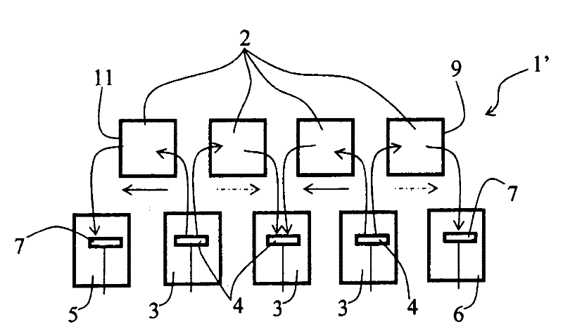
[0032] exist image 3 with Figure 4 The heat generator 1 shown in is realized according to the first embodiment of the invention. It comprises two thermal modules 1' each comprising some magnetocaloric elements 2 arranged in a line. The common chamber 3 , comprising a piston 4 forming a forced flow of heat-carrying fluid, is located each time between two adjacent magneto-caloric elements 2 . In addition, said thermal module 1' also comprises two end chambers 5 and 6 located at the hot end 9 and the cold end 11 of said thermal module 1' and each also comprising a piston forming a flow-through part 7.

[0033] Each magneto-caloric element 2 is adapted to flow through a heat transfer fluid driven by pistons 4, 7 and is subjected to magnetic field variations by means of magnetic means (not shown) that produce alternating heating and cooling cycles. The movement of the pistons 4...


PUM


Abstract

The present invention relates to a thermal generator (1) that comprises at least one thermal module (1') including at least two adjacent magnetocaloric members (2), a common distribution chamber (3) combined with a coolant circulation means (4) fluidically connecting said magnetocaloric members (2) together, and two end chambers (5, 6) also combined with a circulation means (7) and each fluidically connected to the two magnetocaloric members (2) located at the hot (9) and cold ends of said thermal module (1'), and a magnetic arrangement for subjecting each magnetocaloric member (2) to a variable magnetic field, wherein said thermal generator (1) is characterised in that said circulation means (4) combined with said common distribution chamber (3) moves the coolant simultaneously through the two adjacent magnetocaloric members (2) in different directions.

Description

technical field [0001] The invention relates to a heat generator comprising at least one thermal module comprising at least two adjacent magneto-caloric elements arranged to be passed through by a heat-carrying fluid, associated with a flow-through part of the heat-carrying fluid and making the said adjacent magneto-caloric elements in fluid communication with each other, and two chambers also associated with flow-through components and in fluid communication with the magneto-caloric elements located at the ends of said thermal module, called hot and cold ends, respectively. an end chamber; and magnetic means for subjecting each magneto-caloric element to a variable magnetic field whereby cycles of heating and cooling are alternately produced in each magneto-caloric element, through which flow-through components are carried out synchronously with changes in the magnetic field. flow of thermal fluid through the magnetocaloric element. Background technique [0002] Magnetic r...

Claims


Application Information

Patent Timeline
Patent Type & Authority Applications(China)
IPC IPC(8): H01L37/04F25B21/00F25B29/00
CPCF25B21/00F25B2321/002H01L37/04Y02B30/66Y02B30/00H10N15/20F25B29/00
Inventor J-C·埃茨勒C·米勒
Owner COOLTECH APPL SAS
Learn More