Multi-modal system for detection and control of changes in brain state
a multi-modal system and brain state technology, applied in the field of medical treatments, can solve the problems of increasing the pressure required to circulate coolant, cumbersome and costly manufacturing, etc., and achieve the effects of reducing the risk of tissue injury, facilitating verification of placement, and increasing precision
- Summary
- Abstract
- Description
- Claims
- Application Information
AI Technical Summary
Benefits of technology
Problems solved by technology
Method used
Image
Examples
embodiment 60
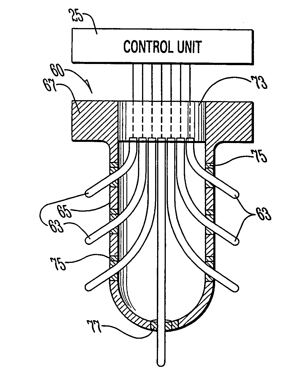
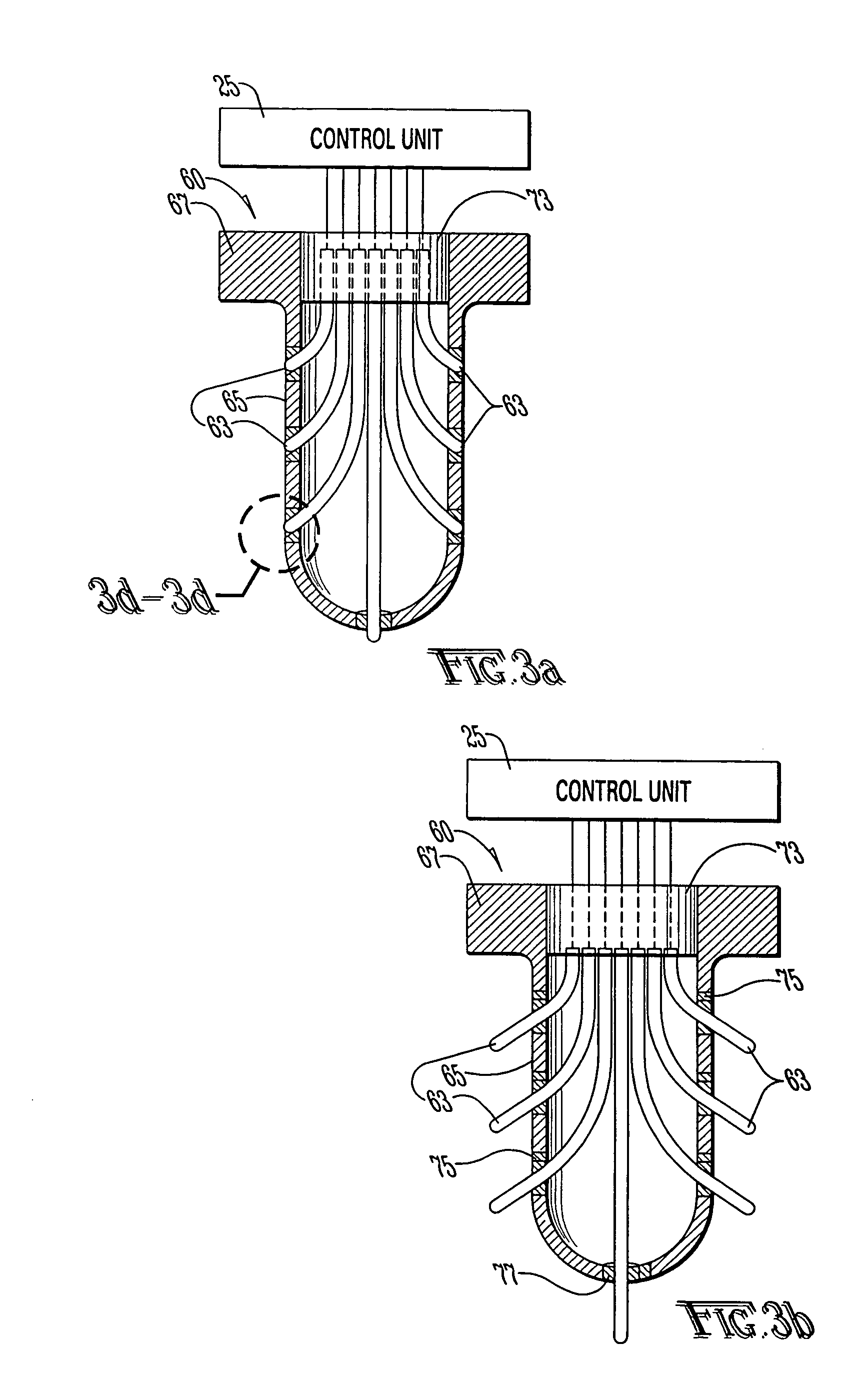
[0079]FIGS. 3a–3b depict a modified embodiment 60 of the present invention wherein extendable elements 63 can be extended into the surrounding tissue after a shaft portion 65 of the device 60 is implanted into a desired target region or tissue. The device structure 60 of this embodiment includes a base portion 67. The shaft portion 65 is first inserted into the target tissue after which the extendable elements 63 can be selectively extended into the surrounding tissue to thereby increase the contact area between the extendable elements 63 and the tissue, wherein the extendable elements 63 are extended either manually or by using tiny motors or other mechanical, magnetic or electromechanical means. Each of the extendable elements 63 used for cooling therapy, sometimes referred to herein as a cooling element 63, is hollow and made of biocompatible materials with high thermal conductivity such as gold, platinum, or other suitable thermally conductive material and may include a dividing...
embodiment 200
[0086]Another modified embodiment 200 of the multi-purpose device of the present invention for simultaneous sensing and control of changes in brain state and cooling of brain tissue is depicted in FIGS. 7a through 7c. Many of the features of the modified device are substantially similar to those hereinbefore described. As a result, repetitive descriptions thereof will not be reiterated here in detail.
[0087]Device 200 comprises a proximal end 211 and a distal end 213, wherein the proximal end 211 is operatively positioned closer to the skull than the distal end 213. The proximal end 211 and the distal end 213 are housed in a shaft portion 215. Device 200 includes at least one spiral hollow tube or conduit 217 for carrying a coolant or a refrigerant 219 from a reservoir (not shown) located external to the device 200 into the conduit 217. The conduit 217 has a helix or spiral configuration which operatively increases the surface area thereof to thereby maximize heat transfer between th...
embodiment 410
[0093]Other modified embodiments of the unitized device with three-dimensional capabilities for sensing and control of brain state changes are depicted in FIGS. 10A through 10C. Embodiment 410, shown in FIGS. 10A–10C and 11 and similar to the embodiment shown in FIGS. 3 and 8, comprises a main solid shaft 413 having a proximal end 415 that is generally operatively positioned closer to the skull than a distal end 417 thereof. A plurality of hollow tubes or conduits 419 are positioned internally within the main shaft 413 to provide fixed paths for guided deployment of elements such as tubes (for carrying the coolant or the refrigerant) or wires 421 for multi-dimensional acquisition of signals (electrical, physical, chemical, etc.) as hereinbefore described via contacts / sensors 423 at the tips or anywhere along the exposed elements 421. These hollow tubes or conduits are made by boring holes into the shaft and these conduits open out of the shaft at different distances 433 and 435 from...
PUM
 Abstract
Description
Claims
Application Information
 - R&D
- Intellectual Property
- Life Sciences
- Materials
- Tech Scout
- Unparalleled Data Quality
- Higher Quality Content
- 60% Fewer Hallucinations
Browse by: Latest US Patents, China's latest patents, Technical Efficacy Thesaurus, Application Domain, Technology Topic, Popular Technical Reports.
© 2025 PatSnap. All rights reserved.Legal|Privacy policy|Modern Slavery Act Transparency Statement|Sitemap|About US| Contact US: help@patsnap.com


