Air conditioning control system for variable evaporator temperature

a control system and variable evaporator technology, applied in the field of air conditioning control system for variable evaporator temperature, can solve the problems of energy waste, complex incompatibility, undesirable effect of high coolant flow rising above known standards, etc., and achieve the effect of increasing the range of acceptable cooling coil performance between peak and minimum

Inactive Publication Date: 2001-08-07
SMAC TECH
View PDF13 Cites 175 Cited by
  • Summary
  • Abstract
  • Description
  • Claims
  • Application Information

AI Technical Summary

Benefits of technology

.Tables 3 and 4 are very special cases involving an outside air condition which has a dew point temperature below that of the dew point temperature of the supply air. This will be discussed when the new "humidity Economy Cycle" of this system will be explained on page 18.

Problems solved by technology

In explaining this invention I observe that there is complex incompatibility in relationships between heat and mass transfer, limitations applied to maintain turbulent coolant flow performance at the heat exchangers and the problems arising when a ratio of internal sensible heat loads to internal total heat loads present a design problem.
Factors which can pose problems in capacity control include lag between simultaneous dehumidification and cooling processes, and instability arising from coolant flow which has fallen from turbulent to transition flow when a total load falls to about 30% to 50% below peak cooling loads.
There is also an undesirable effect of high coolant flow rising above known standards.
Use of systems dependent solely on throttling the refrigerant as the capacity control means are not preferred nor hot gas bypass because of their implicit inefficiency.
The consequence is an energy wasteful system.
Unfortunately this is a very popular system in medium and low humidity climates.
This means that smaller internal room loads are over cooled.
Nevertheless, it is still wasteful since the larger return air portion of the outside air, return air combination had been over cooled unnecessarily.
In the absence of reheating, the treated space is often too cold for comfort for the occupants dressed in their summer attire.
This is not possible over the usual cooling season climatic range when the supply temperature is fixed.
A further small fall in load would result in unstable performance into transition flow where the Reynolds number is below 2300 and the coolant velocity is below 0.2 m / s.

Method used


Image

  • Air conditioning control system for variable evaporator temperature
  • Air conditioning control system for variable evaporator temperature
  • Air conditioning control system for variable evaporator temperature

Examples


Embodiment Construction

Examples of the invention are described hereunder in some detail with reference to, and are illustrated in, the accompanying drawings and charts wherein:

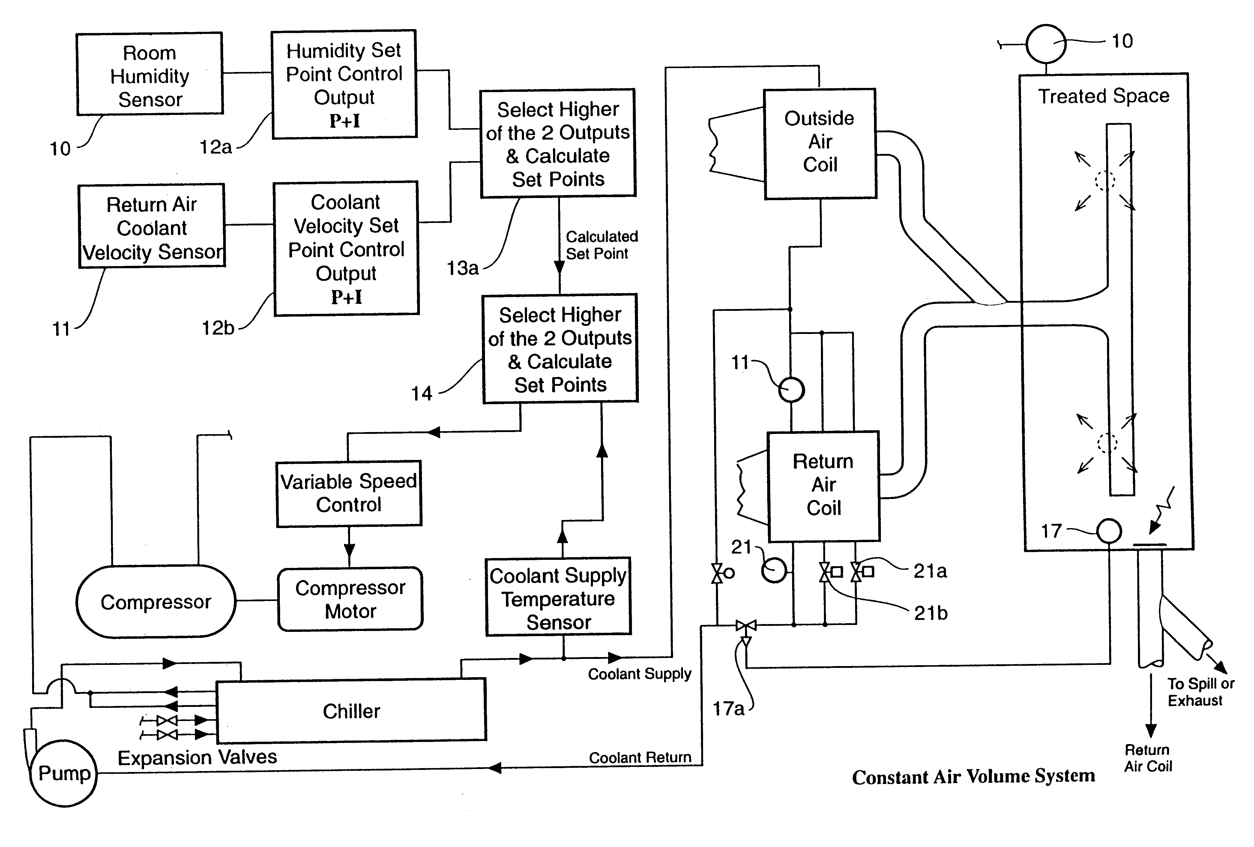
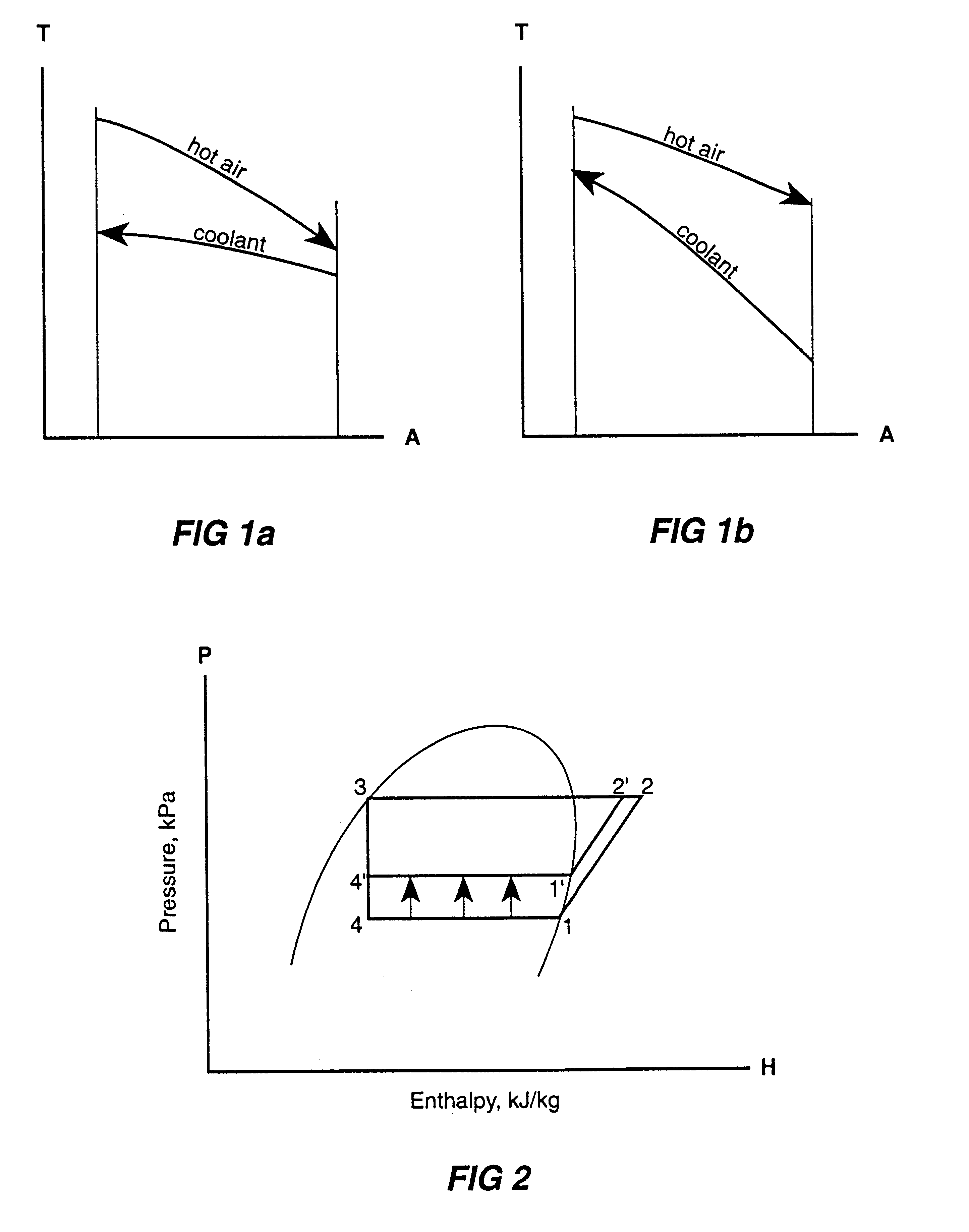
FIG. 1(a) refers to the performance of the outside air coil in the arrangement of separate outside air and return air coils discussed in detail above on page 5 beginning with line 10. It is of advantage where a significant outside air percent of the supply air of about 15% or more is required. Otherwise a modified arrangement of outside air plus return air coil should be considered.

FIG. 1(b) represents a conventional outside air coil performance where the coolant supply flows in parallel to the outside air and return air coil.

FIG. 2 shows this pressure enthalpy diagram to demonstrate the higher evaporator temperature / pressure that can be achieved through this invention over numerous conditions over its operating range and thus substantially reduces the enthalpy difference across the compressor;

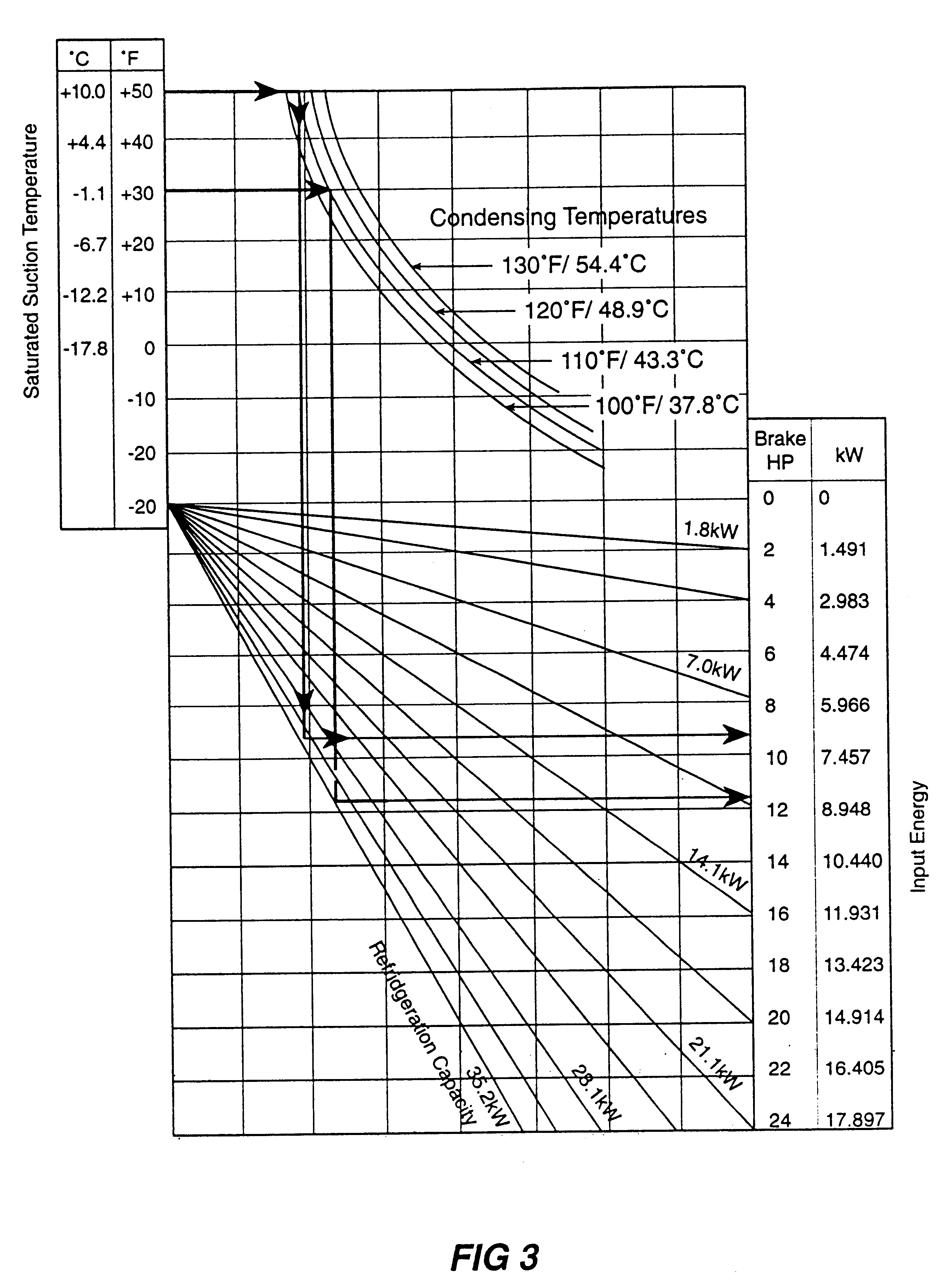
FIG. 3 is a compressor horsepower selec...


PUM


Abstract

A system and method of control of refrigerant air conditioning including a humidity input sensor, and a coolant velocity sensor, using a control system set with a set point whereby to maintain a maximum evaporator temperature set point varying to suit each heat and moisture load condition over a range of conditions compatible with high engineering standards of performance.

Description

This invention relates to air conditioning improvements.An object of this invention is to assist in reducing energy required to effect air conditioning while obtaining high performance standards over the full operating range. Environment control by air conditioning means involves more than simply increase or decrease of the total capacity, but rather, dependent on the relative values of latent heat which are to be simultaneously offset in a manner that the lag in the process of mass transfer behind heat transfer does not contribute an energy penalty.The problem to which this invention is directed is the problem of how to reduce energy required to effect acceptable refrigerant air conditioning for comfort purposes. The system presented here resolves the chaos arising from the contradictory effects of numerous variables in infinite combinations which are involved in refrigerated air conditioning design. Two of these unrelated variables, sensible and latent heat appear in both the room...

Claims


Application Information

Patent Timeline
Patent Type & Authority Patents(United States)
IPC IPC(8): F24F11/00F25B49/02
CPCF24F11/008F24F11/0015F25B49/025F24F11/30F24F2110/20F24F11/83F24F11/84
Inventor SHAW, ALLAN
Owner SMAC TECH
Why Eureka
Try Eureka