Seam welding method and machine therefor

A technology of seam welding and seam welding, which is applied in the field of seam welding and the machine used for it, can solve problems such as spatter, and achieve the effect of avoiding spatter

Inactive Publication Date: 2011-09-28
HONDA MOTOR CO LTD
View PDF6 Cites 14 Cited by
  • Summary
  • Abstract
  • Description
  • Claims
  • Application Information

AI Technical Summary

Problems solved by technology

In this case, however, so-called spatter (scattering of the molten workpiece) is possible

Method used


Image

  • Seam welding method and machine therefor
  • Seam welding method and machine therefor
  • Seam welding method and machine therefor

Examples


Embodiment Construction

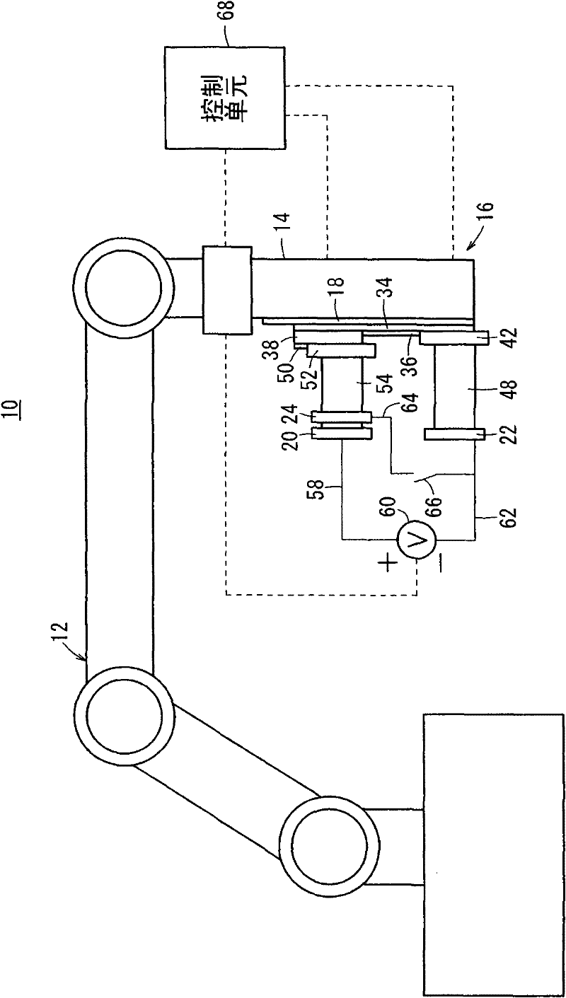
[0054] A detailed description of an exemplary embodiment of a seam welding method and a seam welding machine for performing the seam welding method according to the present invention will be described as follows with reference to the accompanying drawings.

[0055] figure 1 is a schematic side front view showing the whole of the seam welding machine 10 according to the first exemplary embodiment. The seam welding machine 10 includes an articulated robot 12 and a seam welder 16 supported on a distal arm 14 of the articulated robot 12 . The components of the seam welding machine 10 constituted by the combination of the articulated robot 12 and the seam welding machine 16 are well known, as disclosed in Japanese Patent Laid-Open No. 2007-167896 and Japanese Utility Model Registration No. 3124033. Therefore, no detailed description regarding the arrangement of such components is given here.

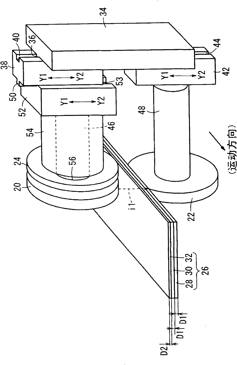
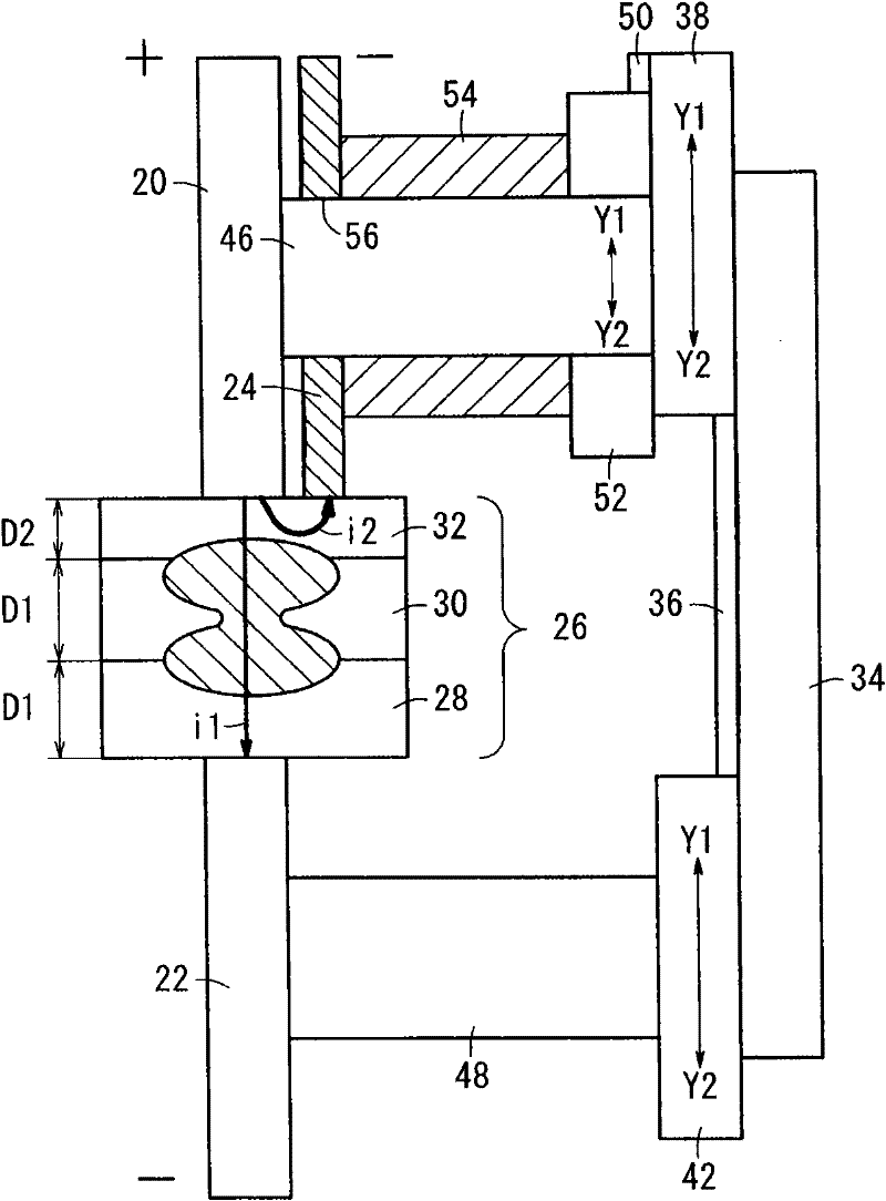
[0056] Such as figure 2 (this is a partial sectional perspective view) and image 3 ...


PUM


Abstract

A seam welding machine (10) includes a first roller electrode (20) and a second roller electrode (22) that hold a layered body (26) formed by layering a plurality of workpieces (28, 30, 32). The first roller electrode (22) is in contact with a thinnest workpiece (32), which is disposed on an outermost side of the layered body. The seam welding machine (10) has a current-branching electrode (24) held in contact with the thinnest workpiece (32), and which is charged with a polarity opposite to that of the first roller electrode (20). Accordingly, when an electric current is applied between the first roller electrode and the second roller electrode that hold the layered body, a branch electric current is applied from the first roller electrode to the current-branching electrode, or a branch electric current is applied from the current-branching electrode to the first roller electrode.

Description

technical field [0001] The present invention relates to a seam welding method and a machine for the same, for seam welding a laminated body (layered body) produced by laminating three or more workpieces, the thinnest with the smallest thickness The workpiece is disposed on the outermost side of the laminate. Background technique [0002] Seam welding is well known as a method for joining metal sheets. As disclosed in Japanese Patent Laid-Open Publication No. 2007-167896 and Japanese Utility Model Registration No. 3124033, during seam welding, a pair of roller electrodes is held between laminated metal sheets (which form a laminate) After that, the current is applied between the roller electrodes. In other words, an electric path is formed in the laminate along its lamination direction. It should be understood that the current from the positive electrode reaches the negative electrode after sequentially passing through the metal plate in contact with the positive electrode...

Claims


Application Information

Patent Timeline
Patent Type & Authority Applications(China)
IPC IPC(8): B23K11/06B23K11/30
CPCB23K2203/04B23K11/002B23K11/061B23K2103/04
Inventor 金子贡长谷川荣作后藤彰
Owner HONDA MOTOR CO LTD
Why Eureka
Try Eureka