Buffer valve

A buffer valve and slide valve technology, applied in the field of buffer valves, can solve problems such as buffer valve failure and limited space in the oil storage chamber, and achieve the effect of accelerating oil discharge speed and shortening recovery time

Active Publication Date: 2011-09-28
宁波恒通诺达液压股份有限公司
View PDF9 Cites 10 Cited by
  • Summary
  • Abstract
  • Description
  • Claims
  • Application Information

AI Technical Summary

Problems solved by technology

The space of the oil storage chamber is limited in its structure, once the oil storage chamber is filled with oil, the buffer valve will fail

Method used


Image

  • Buffer valve
  • Buffer valve
  • Buffer valve

Examples


Embodiment Construction

[0019] Embodiments of the present invention will be further described below in conjunction with the accompanying drawings.

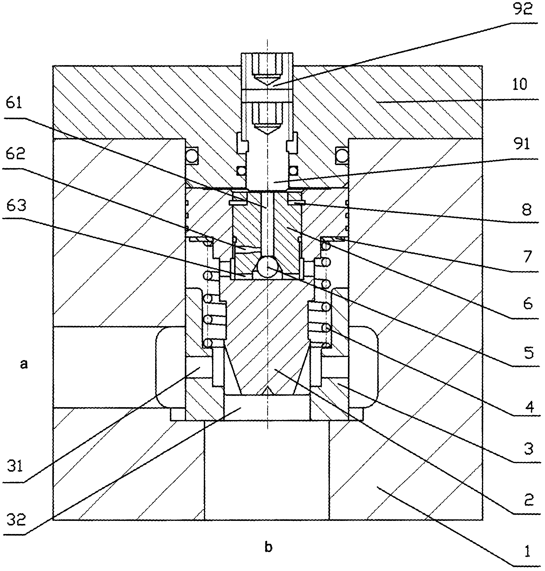
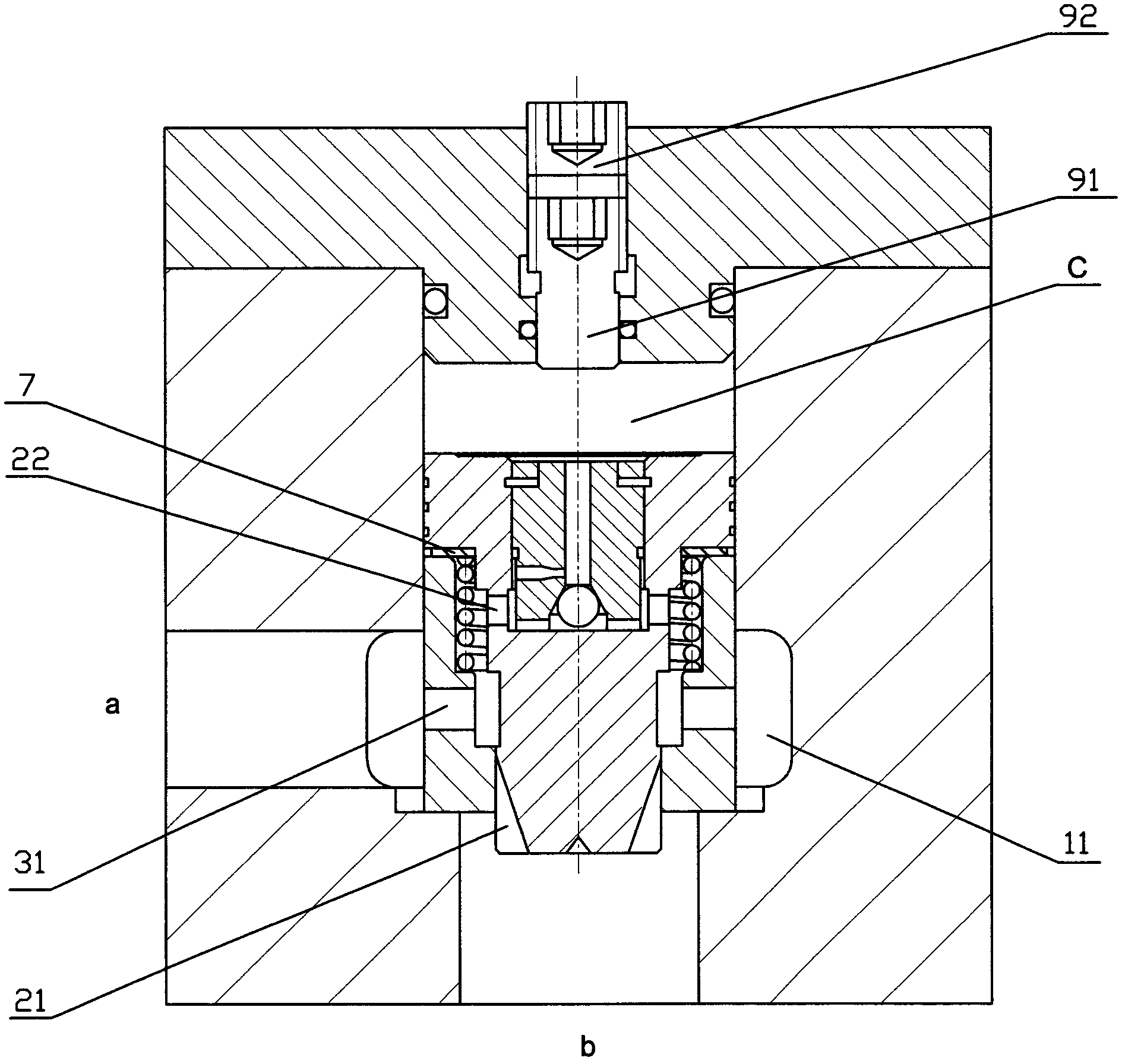
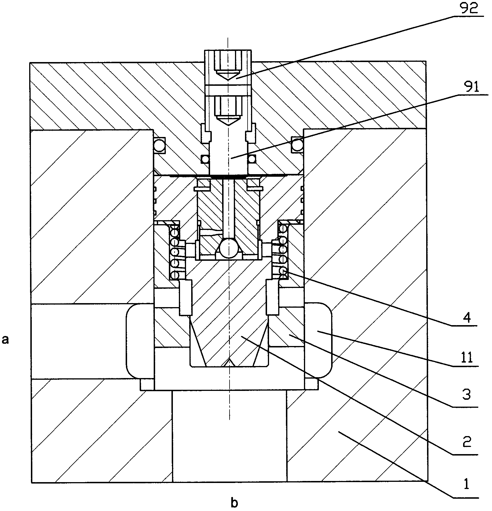
[0020] Such as figure 1 , figure 2 As shown, a buffer valve is composed of a housing 1, a top cover 10, a slide valve 2, a valve seat 3, a spring 4 and an inner core 6 installed in the housing. There is an oil inlet a on the side wall of the housing 1. mouth, and the bottom has oil outlet b. There is an annular groove 11 in the housing, and the annular groove communicates with the a port.

[0021] A valve seat 3 is installed in the valve seat hole in the housing 1, and the valve seat can slide up and down in the valve seat hole. There is a spool valve hole 32 with a step in the center of the valve seat 3, and four guide holes 31 are arranged on the side wall, respectively communicating with the annular groove 11 and the spool valve hole 32 on the housing.

[0022] The inner core 6 is a cylinder with a through hole 61 in the center. The bottom of the...


PUM


Abstract

The invention relates to a buffer valve used in a hydraulic system of a crane. While the crane in a hanging state falls, large-flow oil pressure can be diverted effectively; and after short-time buffer, the buffer valve closes automatically, thus the rotation speed of a motor can be adjusted accurately along with the oil pressure. The buffer valve is composed of a shell, a top cover and a valve plug installed in the shell; the valve plug comprises a slide valve, a valve seat, a spring and an inner plug; the end socket of the slide valve is provided with a wedge-shaped hole; the wedge-shaped hole is communicated with a flow guide hole on the side wall of the valve seat; the inner plug is internally provided with a check valve; the side wall of the inner plug is provided with a damping hole; when oil applied with high pressure enters an oil cavity between the slide valve and the top cover slowly through a damping hole, the slide valve is pushed to slide downward in the valve seat, and the buffer valve is closed gradually; and when a hanged object falls off the ground, the oil pressure of an oil duct decreases, the oil in the oil cavity is extracted rapidly from the inner plug, and the buffer valve restores to the open state automatically.

Description

Technical field [0001] The invention relates to a hydraulic control element, in particular to a self-closing buffer valve used on a crane. Background technique [0002] In a traditional hydraulic control system, such as the hydraulic system of a crane, the forward and reverse circuits of the hydraulic motor have a symmetrical structure. When the hydraulic motor rotates forward, the crane lifts; when the hydraulic motor reverses, the crane descends. After the crane lifts the heavy object, from the moment of hovering to the descent, the load of the heavy object is supported by the high-pressure oil in the hydraulic motor. Due to the change of the pressure of the hydraulic motor, it will have a serious impact on the hydraulic system and the hydraulic motor in an instant. Impairment of hydraulic motor life. A common solution is to connect a flow-limiting shock valve in series on the oil circuit of the hydraulic motor or connect a shock valve in parallel to absorb excessive flo...

Claims


Application Information

Patent Timeline
Patent Type & Authority Applications(China)
IPC IPC(8): F15B13/02
Inventor 杨钊
Owner 宁波恒通诺达液压股份有限公司
Why Eureka
Try Eureka