

Energy-saving system of excavator
An energy-saving system and excavator technology, applied in earth movers/shovels, construction, etc., can solve the problems of many transmission links, low energy utilization efficiency, and affecting the control performance of the whole machine, so as to achieve high transmission efficiency and high energy efficiency The effect of using
- Summary
- Abstract
- Description
- Claims
- Application Information
AI Technical Summary
Problems solved by technology
Method used
Image

Examples
Embodiment Construction
[0014] The present invention will be further described below in conjunction with accompanying drawing.
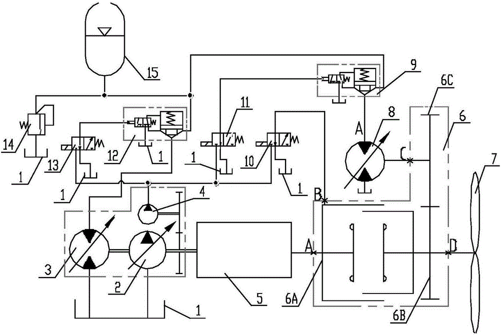
[0015] Such as figure 1 As shown, an energy-saving system for an excavator is mainly composed of an engine direct-drive fan drive circuit, an accumulator-controlled fan motor circuit, and an accumulator-controlled drive motor circuit, including a fuel tank 1, a variable hydraulic pump 2, and a first variable hydraulic motor 3. Quantitative hydraulic pump 4, engine 5, transfer case 6, fan 7, second variable motor 8, first on-off valve 9, first directional valve 10, second directional valve 11, second on-off valve 12, third Directional valve 13, pressure valve 14 and accumulator 15, described engine direct drive fan transmission loop is made of engine 5, transfer case 6, fan 7 and first directional valve 10, and described accumulator control fan motor circuit is composed of The accumulator 15, the first on-off valve 9, the second variable motor 8 and the second directional v...
PUM
 Abstract
Description
Claims
Application Information