Delayed control transfer circuit and power supply system

A conversion circuit and hysteresis control technology, which is applied in the electronic field, can solve problems such as errors and unstable output voltage values, and achieve the effect of eliminating output voltage errors and improving output voltage accuracy

Active Publication Date: 2011-09-28
HUAWEI TECH CO LTD
View PDF7 Cites 15 Cited by
  • Summary
  • Abstract
  • Description
  • Claims
  • Application Information

AI Technical Summary

Problems solved by technology

[0005] The embodiment of the present invention is to provide a hysteresis control conversion circuit and power supply system, which solves the defect of error between the output voltage and the expected output voltage caused by the unstable output voltage value in the actual circuit, and eliminates the output voltage of hysteresis BUCK Error problem, improve the output voltage accuracy of hysteresis BUCK

Method used


Image

  • Delayed control transfer circuit and power supply system
  • Delayed control transfer circuit and power supply system
  • Delayed control transfer circuit and power supply system

Examples


Embodiment Construction

[0015] In order to make the purpose, technical solutions and advantages of the embodiments of the present invention clearer, the technical solutions in the embodiments of the present invention will be clearly and completely described below in conjunction with the drawings in the embodiments of the present invention. Obviously, the described embodiments It is a part of embodiments of the present invention, but not all embodiments. Based on the embodiments of the present invention, all other embodiments obtained by persons of ordinary skill in the art without creative efforts fall within the protection scope of the present invention.

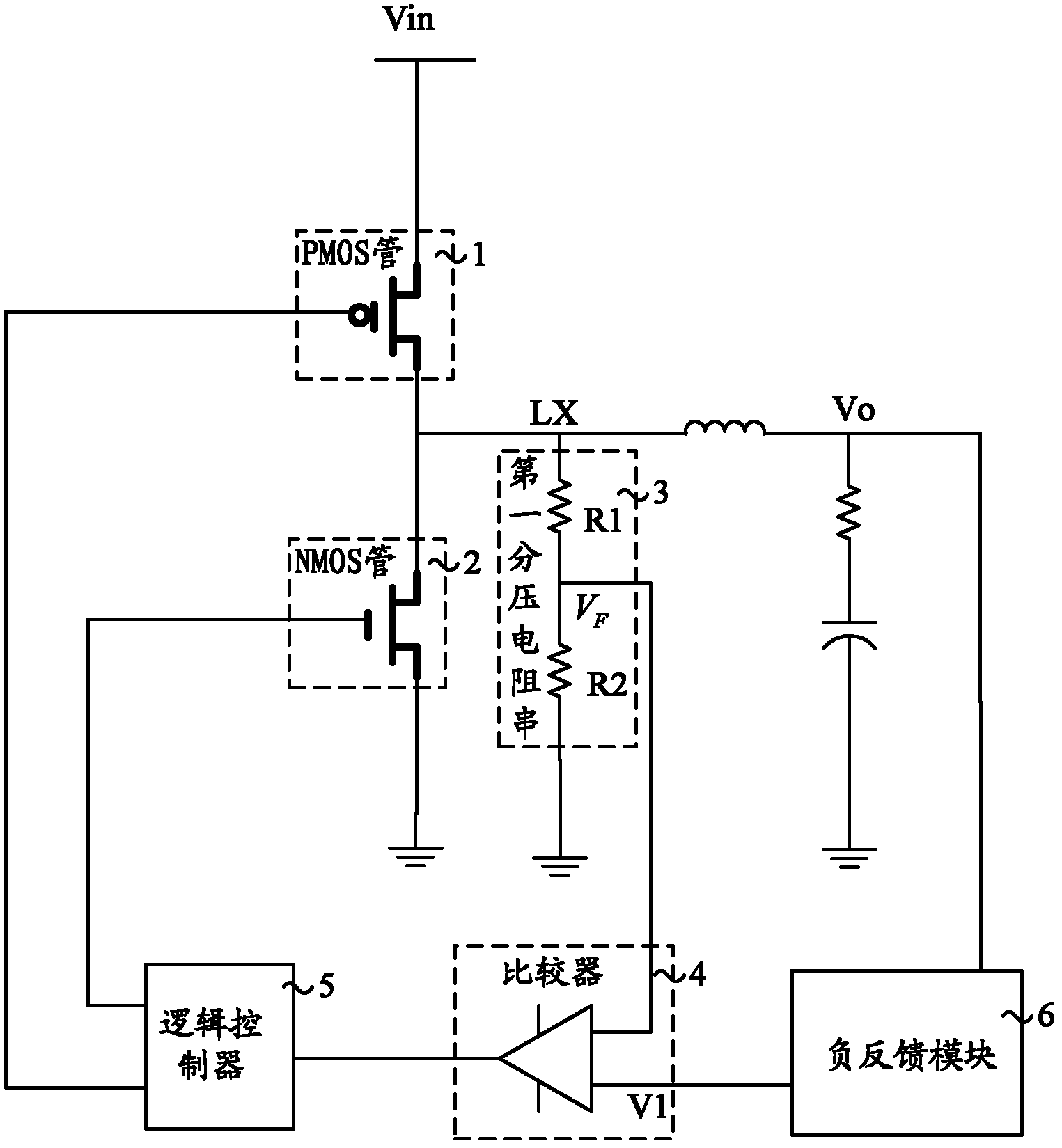
[0016] figure 2 It is a structural schematic diagram of Embodiment 1 of the hysteresis control conversion circuit of the present invention, as shown in figure 2 As shown, this embodiment provides a hysteresis control switching circuit, which may specifically include a PMOS transistor 1 , an NMOS transistor 2 , a first voltage dividing resistor ...


PUM


Abstract

The invention discloses a delayer control transfer circuit and a power supply system. The circuit includes a PMOS transistor and an NMOS transistor connected in series between a voltage input terminal and an earthling terminal, a first divider resistance series, a comparator and a logic controller connected in series between a voltage output terminal and the earthling terminal, wherein an output terminal of the comparator is connected to an input terminal of the logic controller, and two output terminals of the logic controller are respectively connected to the grids of the PMOS transistor and the NMOS transistor. The circuit also includes a negative feedback unit which is connected between the voltage output terminal and the input terminal of the comparator and used for negative feedbackcontrol of the output voltage of the delayed control transfer circuit and the clamping the output voltage to be a predetermined reference voltage. The invention also provides the power supply system.By the method and the system in the invention, the output voltage error of delayed BUCK is removed.

Description

technical field [0001] The invention relates to electronic technology, in particular to a hysteresis control switching circuit and a power supply system. Background technique [0002] DC to DC (Direct Current-Direct Current; hereinafter referred to as: DC-DC) converter is a voltage converter that effectively outputs a fixed voltage after changing the input voltage. It is currently widely used in mobile phones, MP3, digital cameras, portable media players, etc. product. DC-DC converters are usually divided into buck converters (BUCK), boost converters (BOOST) and buck-boost converters (BUCK-BOOST), where BUCK converts the input DC voltage to a lower output For DC voltage devices, the hysteresis control mode is a control mode of BUCK. [0003] figure 1 It is a structural schematic diagram of a hysteresis control BUCK circuit in the prior art, such as figure 1 As shown, it is a hysteresis control BUCK circuit in the prior art, wherein, a P-channel metal oxide semiconductor ...

Claims


Application Information

Patent Timeline
Patent Type & Authority Applications(China)
IPC IPC(8): H02M3/158
CPCH02M3/156H02M3/158
Inventor 陈亮谢强
Owner HUAWEI TECH CO LTD
Why Eureka
Try Eureka