A Reference Voltage Correction Circuit for Controlling Buck Converter and Its Application

A reference voltage and correction circuit technology, which is applied in the direction of control/regulation systems, instruments, and adjustment of electrical variables, etc., can solve problems such as duty cycle changes, differential linear adjustment rates, etc., and achieve elimination of output voltage errors, fast response, and common mode The effect of a wide input voltage range

Inactive Publication Date: 2017-01-04
南京泰艾微电子有限公司
View PDF8 Cites 0 Cited by
  • Summary
  • Abstract
  • Description
  • Claims
  • Application Information

AI Technical Summary

Problems solved by technology

However, because COT controls the ripple valley of the output voltage, and when the input voltage changes, the duty cycle will change, and the ripple amplitude will also change accordingly, so when the input conditions are different, the output voltage will change accordingly. Changes, showing relatively poor linear adjustment rate (line regulation) indicators, for this reason, the existing COT-controlled DC-DC must be transformed and innovated

Method used


Image

  • A Reference Voltage Correction Circuit for Controlling Buck Converter and Its Application
  • A Reference Voltage Correction Circuit for Controlling Buck Converter and Its Application
  • A Reference Voltage Correction Circuit for Controlling Buck Converter and Its Application

Examples


Embodiment Construction

[0018] The present invention will be further described below in conjunction with accompanying drawing, and the structure and principle of this device are very clear to those skilled in the art. It should be understood that the specific embodiments described here are only used to explain the present invention, not to limit the present invention.

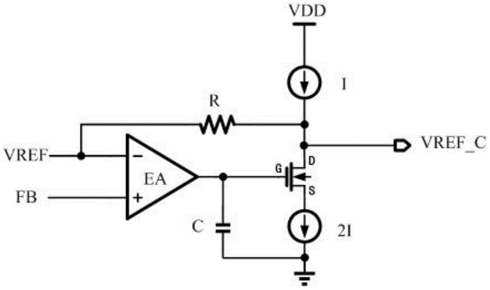
[0019] see figure 1 , the negative input voltage VREF is set at the negative end of the comparator EA, and the non-inverting input voltage FB is set at the positive end of the comparator EA. The source S is connected to the constant current source 2I and the other end of the capacitor C and grounded, the drain D of the field effect transistor is connected to the resistor R1 and one end of the constant current source I, the other end of the resistor R is connected to the input voltage VREF line, and the constant current source I is another One end is equipped with a power supply VDD, the drain of the FET is VREF_C, and VREF_C is the r...


PUM


Abstract

The present invention relates to the technical field of power supplies and correction circuits, in particular to a method and application for controlling a reference voltage correction circuit of a step-down converter. G, the field effect tube source S is connected to the constant current source 2I input signal line, one end of the constant current source 2I output signal line is connected to the other end of the capacitor C and the tap line is grounded, and the field effect tube drain D is the output voltage point C of the comparator VREF , and connected to one end of the resistor R and one end of the output signal line of the constant current source I, the other end of the input signal line of the constant current source I is connected to the power supply VDD, the other end of the resistor R is connected to the reverse input terminal of the comparator EA, and the reverse input of the comparator EA There is a voltage VREF on the end, and a voltage FB is set on the non-inverting input end of the comparator EA. The output voltage C of this circuit is controlled by the voltage VREF and FB. Compared with the prior art, the invention has small input offset voltage, can eliminate the output voltage error caused by the COT structure, and improve the output voltage precision.

Description

[0001] [technical field] [0002] The invention relates to the technical field of power supply and correction circuit, in particular to a reference voltage correction circuit for controlling a step-down converter and its application. [0003] [Background technique] [0004] As we all know, modern circuit systems have an accurate output voltage as the reference for circuit work, and the output voltage is offset by the loss of the circuit and components. The traditional COT-controlled DC-DC directly uses a high-speed comparator (COMP) to control the output voltage, the loop response is very fast, and the output voltage has an extremely fast response to the transient changes of the input voltage and load current. However, because COT controls the ripple valley of the output voltage, and when the input voltage changes, the duty cycle will change, and the ripple amplitude will also change accordingly, so when the input conditions are different, the output voltage will change accordi...

Claims


Application Information

Patent Timeline
Patent Type & Authority Patents(China)
IPC IPC(8): G05F1/56
Inventor 陈超群方俊生顾渊赵文婷
Owner 南京泰艾微电子有限公司
Why Eureka
Try Eureka