
Winding device

A transmission device and retaining device technology, applied in the transmission device, friction transmission device, transportation and packaging, etc., can solve the problems of cumbersome, cores that cannot maintain a constant distance, and bulging

Inactive Publication Date: 2011-10-05
ABB (SCHWEIZ) AG
View PDF4 Cites 0 Cited by
  • Summary
  • Abstract
  • Description
  • Claims
  • Application Information

AI Technical Summary

Problems solved by technology

[0015] However, the method for adjusting the existing tools is very cumbersome to perform and has major drawbacks: only partial winding can be performed on the two long sides of the elongated core and creates a gap between the two wound parts. balance
[0020] Furthermore, due to the use of strips, the rotational movement of the core produced by the strips does not maintain a constant distance between the shuttle and the core or the coil, which causes the wire to be caught on certain parts of the coil, especially in the bends of the core. Bulge
[0021] Therefore, choosing this method entails excess costs associated with the purchase of a coil winder of this type with a set of strips of different lengths and their own different maintenance or repairs (especially replacement strips)

Method used


Image

  • Winding device
  • Winding device
  • Winding device

Examples


Embodiment Construction

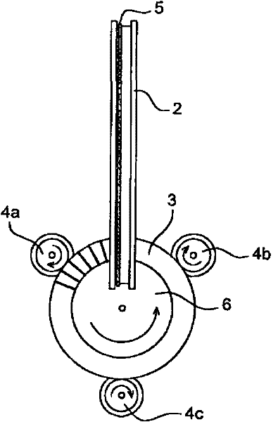
[0060] like figure 1 As shown, a coil winder, which is initially used to wind a core 3 or coil 3' having a toroidal shape, is subsequently adjusted to receive a transmission 1 according to the invention, said coil winder Comprising a shuttle 2 passing through the passage opening 6 of the core or coil 3' and feeding the copper wire 5 to be wound around the core or coil 3', and three drive rollers 4a, 4b and 4c.

[0061] In the following description, the terms "core" 3 and "coil" 3' are used interchangeably to denote a part on which the winding is carried out, with the core 3 in the first coil through the copper wire 5. When the covering layer is completed, it becomes the coil 3'.

[0062] To drive the core 3 or coil 3' in rotation, the three drive rollers 4a, 4b and 4c have gripping surfaces which are placed in contact with the outer contour of the core 3 or coil 3'.

[0063] Drive rollers 4 a and 4 b are provided on both sides of the shuttle 2 , and a third drive roller 4 c ...


PUM


Abstract

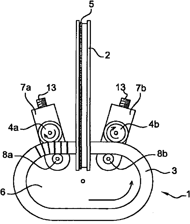
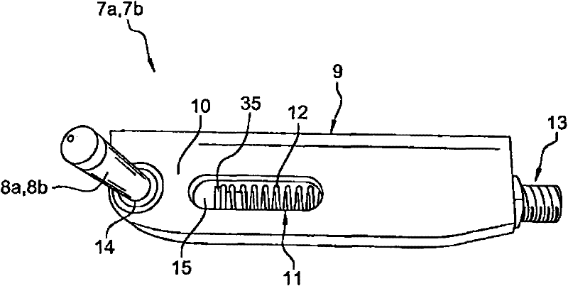
The invention relates to a moving device 1 for a coil 3' core 3 or a coil 3' having a closed shape with an inner contour and an outer contour, including first and second rollers 4a, 4b able to rotate around a respective axis and intended to bear against one of the two contours of the core 3 or of the coil 3', means 20' for driving at least one of said rollers 4a, 4b in rotation, and retaining means 8a, 8b associated with each roller 4a, 4b, the retaining means 8a, 8b being subject to first return means 12 arranged to bring the first retaining means closer to the other of the two contours of the core 3 or the coil 3', as well as a coil winder equipped with such a device.

Description

technical field [0001] The invention relates to a device for moving a coil or a coil core having a closed shape with an inner contour and an outer contour, and a coil winder equipped with such a device. Background technique [0002] Coil winders typically manufacture coils by winding wire, typically copper, and electrically insulated, usually by painting, around a ferromagnetic core, in particular a ferromagnetic core made of soft iron . [0003] Due to the geometry of the core, the coil itself is closed, thereby defining the passage opening. [0004] These coils can be applied by including them in constituent parts of the Hall effect sensor. [0005] The principle of these sensors is based on the change in electrical current created by the entry of a metal rod into the channel opening of the coil. [0006] For this reason, the coils of these sensors most of the time have the shape of a circular ring, allowing a round rod or a rectangular rod to pass through the coil open...

Claims


Application Information

Patent Timeline
Patent Type & Authority Applications(China)
IPC IPC(8): F16H13/02H01F41/06
CPCH01F41/08B65H54/10B65H81/04B65H2701/36
Inventor 阿尔芒多·维拉·博阿斯皮埃尔·库蒂里埃
Owner ABB (SCHWEIZ) AG
Learn More