Instrument for handling a joint component by way of a vacuum

A technology for manipulating parts and instruments, applied in the direction of hip joints, shoulder joints, joint implants, etc., can solve problems that cannot be ruled out

Inactive Publication Date: 2011-10-05
施乐辉骨科用品股份公司
View PDF7 Cites 6 Cited by
  • Summary
  • Abstract
  • Description
  • Claims
  • Application Information

AI Technical Summary

Problems solved by technology

Therefore, it cannot be ruled out that the actuating element of the pressure relief

Method used


Image

  • Instrument for handling a joint component by way of a vacuum
  • Instrument for handling a joint component by way of a vacuum
  • Instrument for handling a joint component by way of a vacuum

Examples


Embodiment Construction

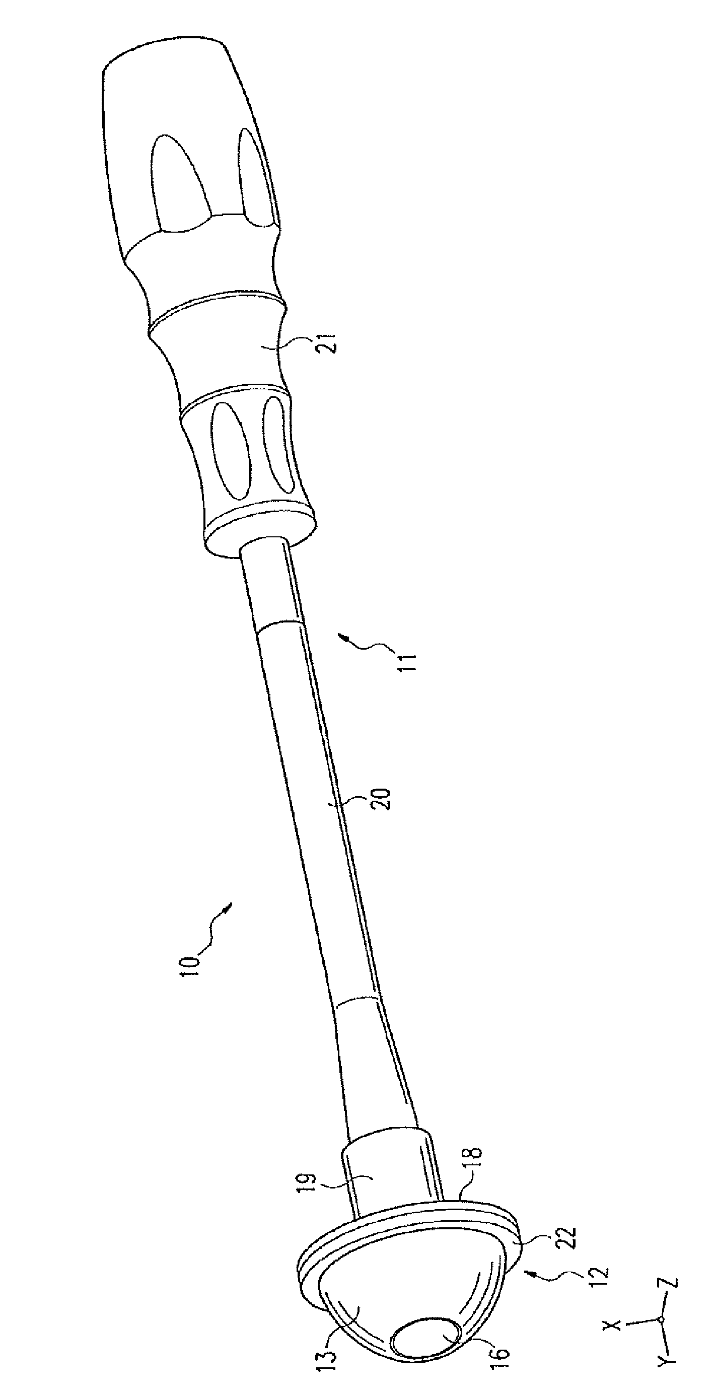
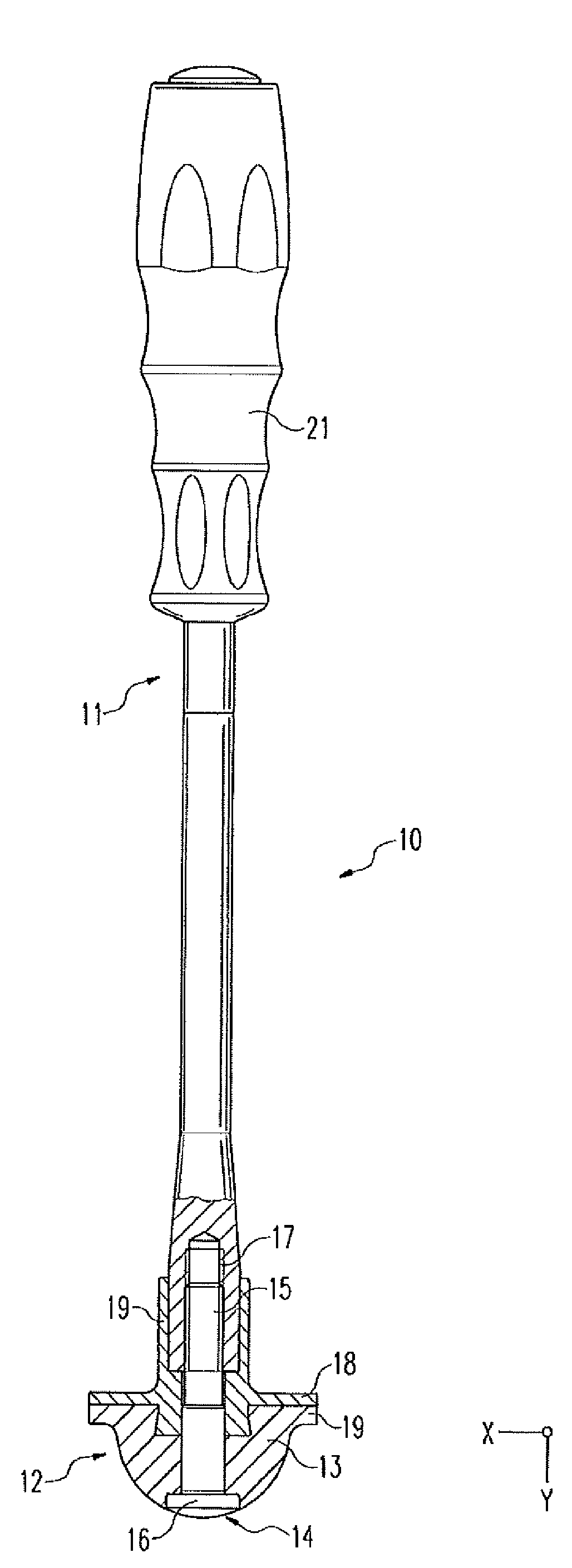
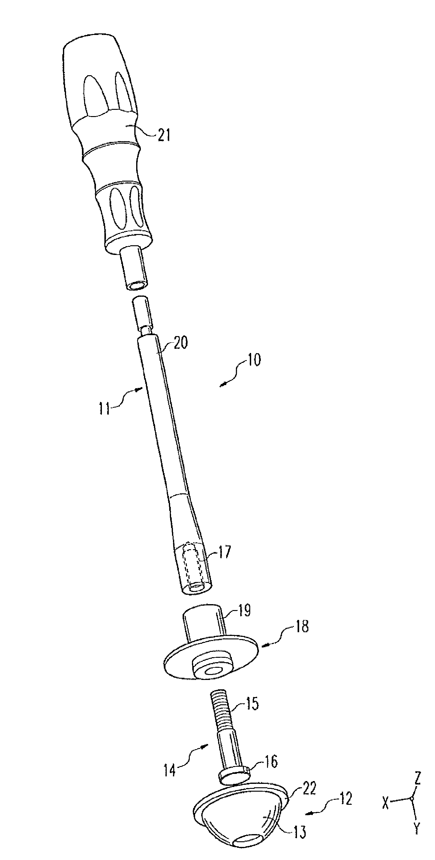
[0016] exist Figures 1 to 3 shows a hip socket inlay placement instrument or a shoulder socket inlay placement instrument, hereinafter simply referred to as placement instrument, which has an operating part 11 and a joint prosthesis not shown here that can be brought into sealing contact, such as a glenoid socket The suction element 12 on the articular surface of the The suction element 12 comprises a soft elastic molding 13 adapted to the articular surface, preferably made of silicone or the like, and which can be deformed by a pulling element in the form of a pulling screw 14, so that During abutment on the articular surface, a negative pressure is generated between the articular surface and the soft elastic molded part 13 . A pulling element in the form of a pulling screw 14 can be actuated from the actuating part 11, as will be explained in more detail below. The soft elastic molded part 13 comprises a hemispherical suction section which is adapted to the concave articu...


PUM


Abstract

The invention relates to a hip or shoulder socket inlay setting instrument (10) comprising a grip section (11) and a suction element (12) that can be laid against the joint surface in a sealing fashion. The suction element (12) comprises a soft flexible molded part (13) tailored to the joint surface, said molded part is capable of being deformed using a pulling element (14) such that an (elevated) vacuum arises between the soft flexible molded part (13) and the joint surface upon abutment thereagainst.

Description

technical field [0001] The invention relates to a device for manipulating a joint part of a joint prosthesis, the joint part comprising an articular surface, in particular a concave joint surface, in particular a hip socket inlay or a shoulder socket inlay placement device , the instrument comprises an operating part and a suction element that can be brought into sealing contact with the articular surface. Background technique [0002] Such devices are generally known. Reference is made in this regard only by way of example to DE 197 04 577 A1, DE 101 28 234 A1 or WO 2007 / 025639 A1. [0003] A suction element in the form of a suction cup is common to all these known placement instruments. These placement instruments have been fully proven in practice. However, they are relatively complex in terms of control technology and also have limited functional reliability. It is also pointed out in the prior art according to DE 101 28 234 A1 and DE 197 22 923 A1 that in each case ...

Claims


Application Information

Patent Timeline
IPC IPC(8): A61F2/46A61F2/30A61F2/00
CPCA61F2/4612A61F2002/4685A61F2002/30616A61F2002/30069A61F2/4609
Inventor M·伊姆霍夫-勒特林R·布拉克
Owner 施乐辉骨科用品股份公司
Why Eureka
Try Eureka