Bubbler

A technology of bubbler and diverter, which is applied in fluid mixers, chemical instruments and methods, mixers, etc. It can solve the problems of insufficient water particles and poor water-saving effect, so as to achieve full water particles and increase jet flow Multiple collision chances, the effect of increasing the jet collision chance

Active Publication Date: 2011-10-12
XIAMEN SOLEX HIGH TECH IND CO LTD
View PDF6 Cites 9 Cited by
  • Summary
  • Abstract
  • Description
  • Claims
  • Application Information

AI Technical Summary

Problems solved by technology

[0003] The present invention provides a bubbler, which overcomes the shortcomings of the bubbler in the background art, such as poor water saving effect and insufficient water particles

Method used


Image

  • Bubbler
  • Bubbler
  • Bubbler

Examples


Embodiment Construction

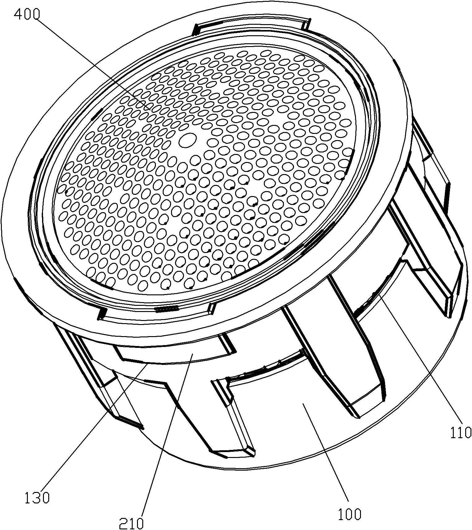
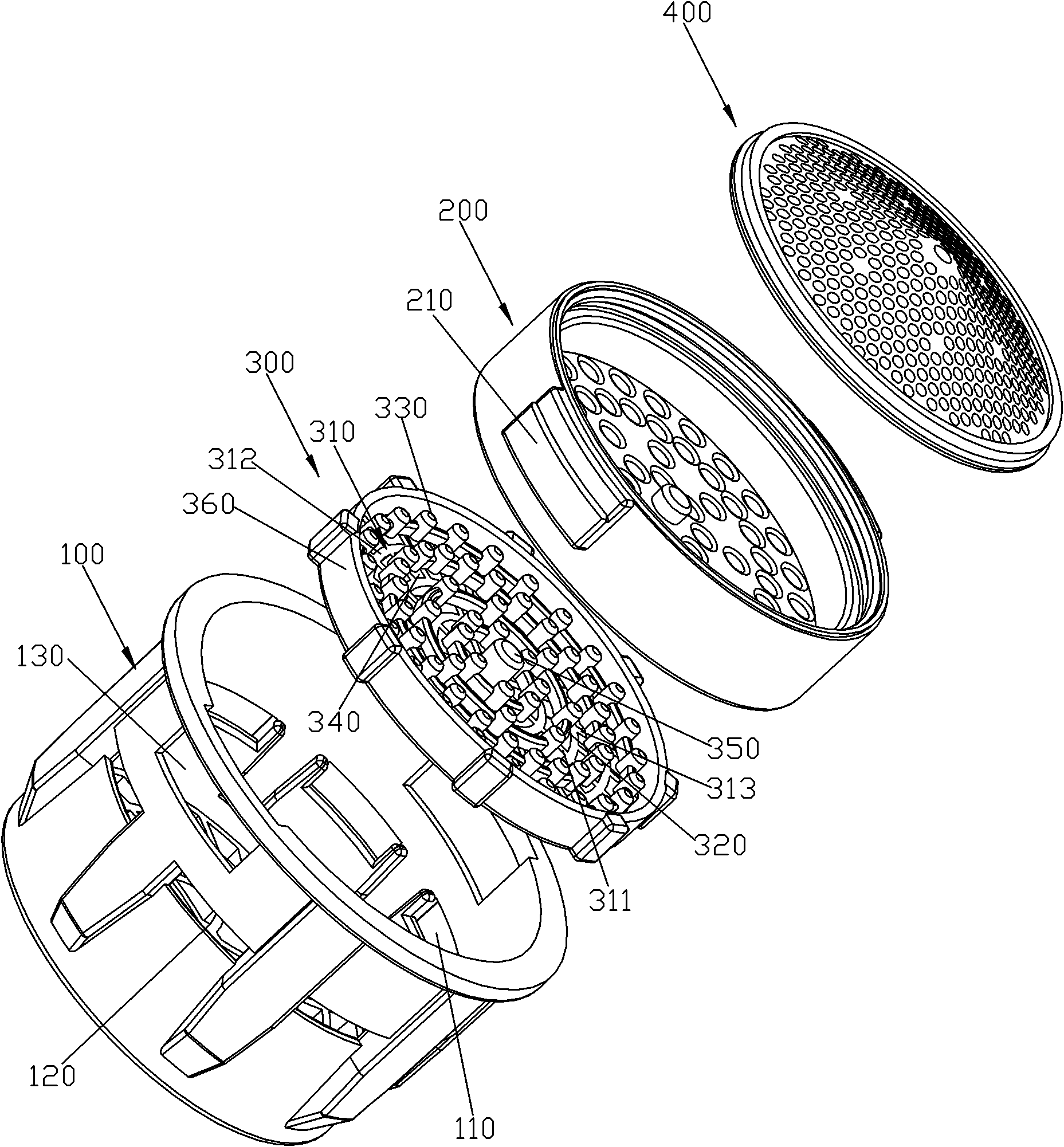
[0028] Please check Figure 1 to Figure 5 , a bubbler, which includes a body 100, a diverter 200, an insert 300 and a filter member 400.

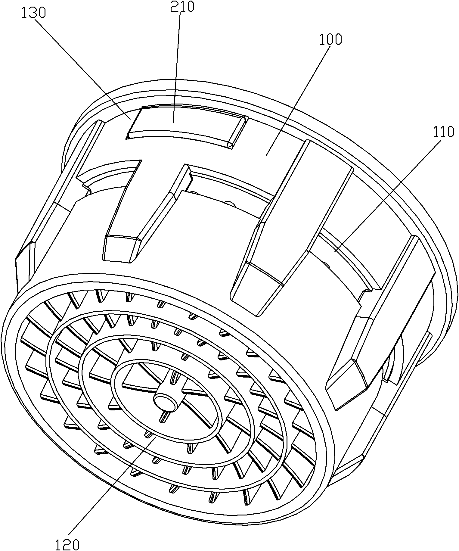
[0029] The body 100 includes a sleeve body and a support frame 120 fixed on the inner turning surface of the bottom of the sleeve body. The sleeve body is provided with a suction hole 110 that runs through the inside and outside of the sleeve. The outer port of the suction hole 110 is located on the outer surface of the sleeve, and the inner port is located on the inner surface of the sleeve, and is located under the flow divider 200 . Moreover, a notch 130 is provided on the part of the sleeve above the suction hole 110 .

[0030] The insert 300 is fitted into the casing of the body 100 and supported on the supporting frame 120 . In order to limit the rotation of the insert 300 relative to the casing, preferably, a protrusion is provided on the outside of the insert 300, and a rotation-limiting groove is provided in the casing, and the p...


PUM


Abstract

The invention discloses a bubbler, comprising a body (100), a flow divider (200) and an inserting member (300), wherein the flow divider (200) and the inserting member (300) are installed in the body (100), the body (100) is provided with an air suction hole (110) penetrating through the inside and the outside, a jet flow is formed by a water flow under the action of the flow divider (200) and collides the inserting member (300) to generate an atomization effect and is mixed with air sucked by the air suction hole (110), the inserting member (300) comprises a plurality of bottom-layer clapboards (310), a plurality of middle-layer clapboards (320) and a plurality of upper-layer convex columns (330) which are fixedly connected together, channels (340) are formed between adjacent bottom-layer clapboards (310) and between adjacent middle-layer clapboards (320), and collision surfaces of the upper-layer convex columns (330), the middle-layer clapboards (320) and the bottom-layer clapboards(310) form three layers at intervals along the direction (X). The bubbler has the advantages of increasing a plurality of jet flow collision chances, has excellent water saving effect and full water granules.

Description

technical field [0001] The invention relates to a bubbler. Background technique [0002] Existing bubblers, such as DE202006003342U1 announced by the German Patent Database, include a housing, a jet decomposition device and a jet adjustment device, the housing is provided with an air suction hole running through the inside and outside, and the jet decomposition device is installed on the Inside the casing, the injection regulating device includes at least one insert inserted into the casing. The insert includes a central column, concentric circular spokes, spokes and an outer ring, the central column and the outer ring are affixed to the spokes, the concentric circular spokes are affixed to the spokes and the upper end surfaces of the concentric circular spokes and the spokes are flush, the Protruding posts are protrudingly provided at the joints of the spokes and the concentric circular bars. The water flow is acted by the spray decomposition device to form a jet flow, an...

Claims


Application Information

Patent Timeline
Patent Type & Authority Applications(China)
IPC IPC(8): B01F5/02B01F3/04
CPCE03C1/084Y02A20/411B01F23/2323B01F25/31232B01F25/31243
Inventor 钟燕辉陈添育刘仰旺周华松
Owner XIAMEN SOLEX HIGH TECH IND CO LTD
Why Eureka
Try Eureka