Bubble former

A technology of bubbler and flow divider, which is applied in fluid mixers, chemical instruments and methods, mixers, etc., can solve the problems of large volume and high cost, and achieve the effect of small volume, low cost, and sufficient air content in water spray

Inactive Publication Date: 2013-04-17
XIAMEN SOLEX HIGH TECH IND CO LTD
View PDF1 Cites 0 Cited by
  • Summary
  • Abstract
  • Description
  • Claims
  • Application Information

AI Technical Summary

Problems solved by technology

[0003] The invention provides a bubbler, which overcomes the disadvantages of high cost and large volume of the bubbler in the background art

Method used


Image

  • Bubble former
  • Bubble former
  • Bubble former

Examples


Embodiment Construction

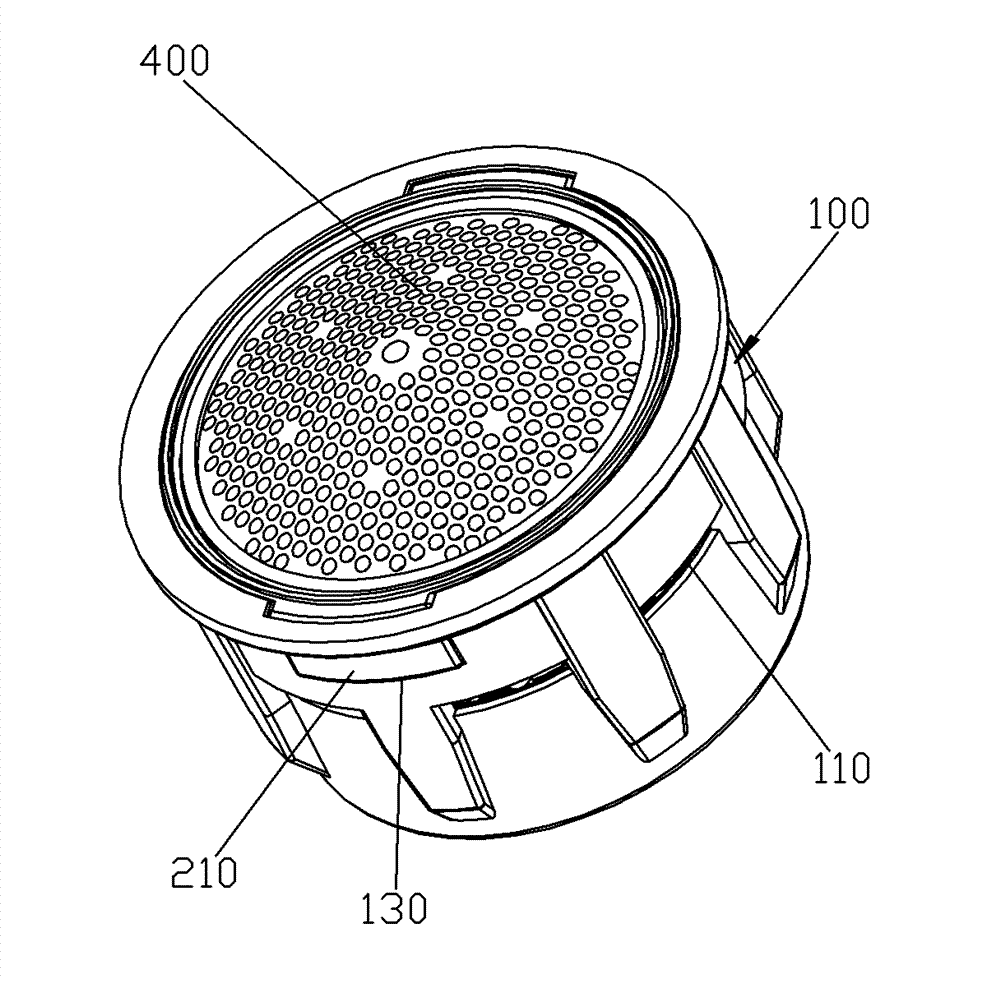
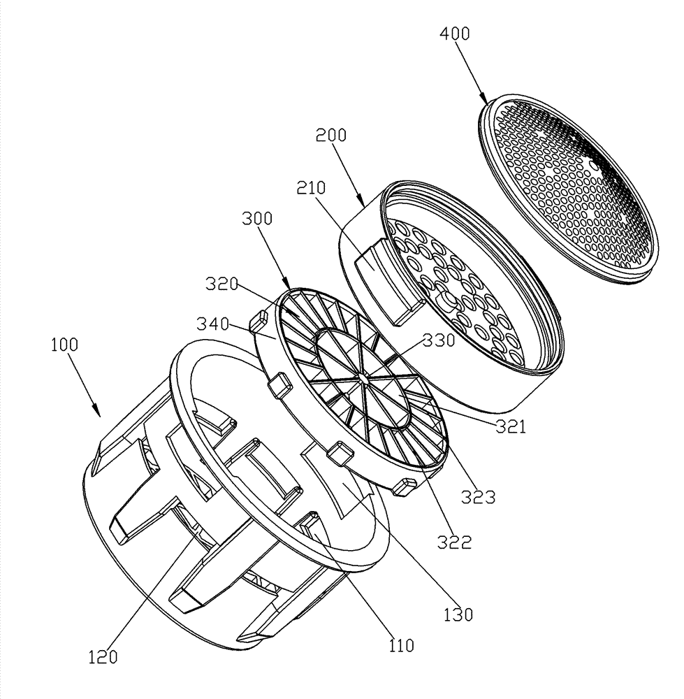
[0026] Please check Figure 1 to Figure 6 , a bubbler, which includes a body 100, a diverter 200, an insert 300 and a filter member 400.

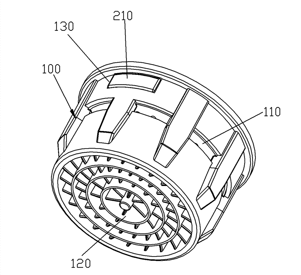
[0027] The body 100 includes a sleeve body and a support frame 120 fixed on the inner turning surface of the bottom of the sleeve body. The sleeve body is provided with a suction hole 110 that runs through the inside and outside of the sleeve. The outer port of the suction hole 110 is located on the outer surface of the sleeve, and the inner port is located on the inner surface of the sleeve, and is located under the flow divider 200 . Moreover, a notch 130 is provided on the part of the sleeve above the suction hole 110 .

[0028] The insert 300 is fitted into the casing of the body 100 and supported on the supporting frame 120 . In order to limit the rotation of the insert 300 relative to the casing, preferably, a protrusion is provided on the outside of the insert 300, and a rotation-limiting groove is provided in the casing, and the p...


PUM


Abstract

Disclosed is an aerator, comprising a body (100), a flow divider (200) and an inserter (300). The inserter (300) and the flow divider (200) are mounted and connected in the body (100). An air suction hole (110) runs through the body (100). A water flow forms a jet flow under the action of the flow divider (200). The jet flow collides with the inserter (300) to incur an atomization effect and is mixed with air sucked by the air suction hole (110). The inserter (300) comprises a plurality of bottom layer ribs (310) and a plurality of top layer ribs (320) fixedly connected together. A collision surface of the bottom layer ribs (310) and a collision surface of the top layer ribs (320) form two layers separated in the direction (X). The aerator has the following advantages. Since the inserter comprises the bottom layer ribs and the top layer ribs and the collision surface of bottom layer ribs and the collision surface of the top layer ribs form two separated layers of collision surfaces, not only a double collision function can be achieved through only one inserter, but also the inserter is small in volume and requires less materials, and the body is simple in structure, low in cost, and convenient for mounting.

Description

technical field [0001] The invention relates to a bubbler. Background technique [0002] Existing bubblers, such as the CN03819912.2 of the Chinese Patent Data Disclosure and Announcement, include a housing, a spray decomposition device and a spray adjustment device. The shell is provided with an air suction hole penetrating inside and outside. The spray decomposition device is installed in the casing. The injection regulating device comprises a plurality of inserts in sequential housings. The inserts all include partitions crossed and fixed together, and the top surfaces of the partitions are flush. The plurality of inserts are arranged along the direction of water flow. The water flow is acted by the spray decomposition device to form a jet flow, and the jet flow collides with the insert to produce an atomization effect, and mixes with the air sucked in by the suction hole. This bubbler has the following disadvantages: using multiple inserts to achieve multiple collis...

Claims


Application Information

Patent Timeline
Patent Type & Authority Patents(China)
IPC IPC(8): B01F5/02
CPCE03C1/084B01F5/0421B01F3/04503B01F5/043B01F23/2323B01F25/31232B01F25/31243
Inventor 钟燕辉陈添育黄祥周华松
Owner XIAMEN SOLEX HIGH TECH IND CO LTD
Why Eureka
Try Eureka