Supercharge Your Innovation With Domain-Expert AI Agents!

Reciprocating hydraulic system

A hydraulic system, reciprocating technology, used in hand-held tools, fluid pressure actuation devices, remote control motors, etc., can solve the problems of easy wear and damage of parts, size and strength limitations, long-term wear and tear and other problems

Inactive Publication Date: 2011-10-12
陈钰霖
View PDF6 Cites 2 Cited by
  • Summary
  • Abstract
  • Description
  • Claims
  • Application Information

AI Technical Summary

Problems solved by technology

[0004] Since the hydraulic tool is generally for the purpose of labor saving, the shaft end of the pressure rod 3 is quite close to the shaft contact point of the input shaft 2, so that the user can easily press the hydraulic pressure generating device 1 to drive the tool set by utilizing the principle of leverage action; in addition, the pressing rod 3 produces circular arc swing with the shaft end as the center, while the input shaft 2 can only move back and forth in the axial direction, resulting in a limited swing range of the pressing rod 3; When the pressing rod 3 is pressed, it can only drive the input shaft 2 to move a short distance; moreover, the connecting rod group 4 is prone to wear after long-term use due to the large number of components, and the size and strength are limited by the installation position. damage and other issues
[0005] Based on the above-mentioned previous technologies, conventional hydraulic tools have problems such as the composition of driving parts, complex assembly, and easy wear and tear of parts.

Method used


Image

  • Reciprocating hydraulic system
  • Reciprocating hydraulic system
  • Reciprocating hydraulic system

Examples


Embodiment Construction

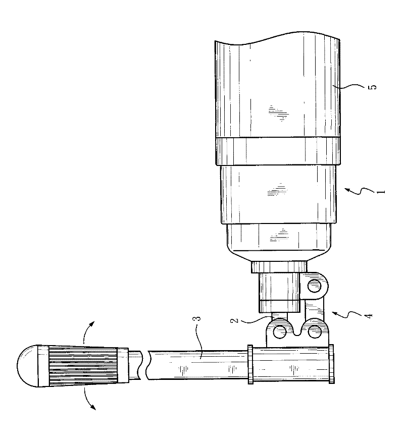
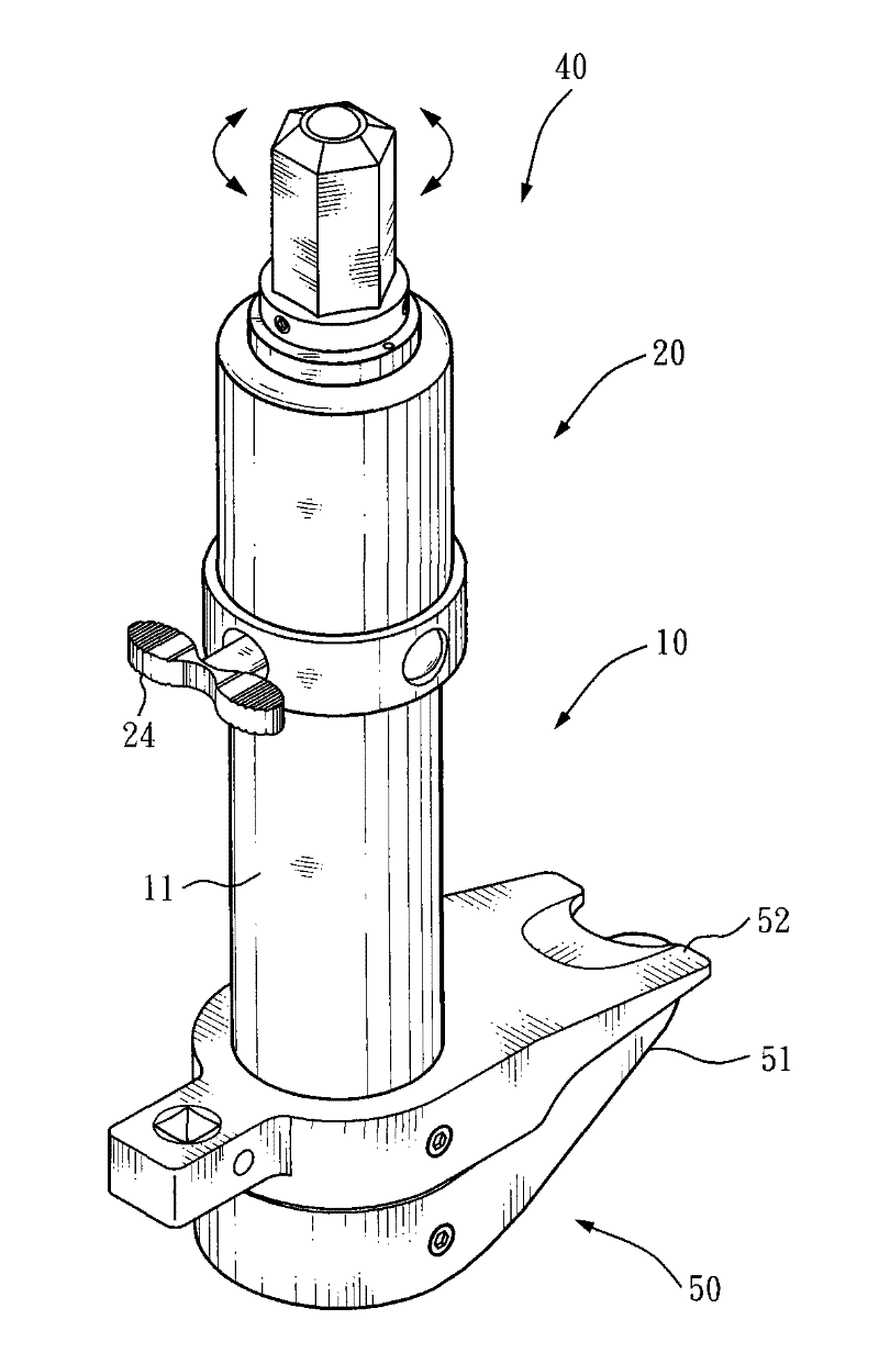
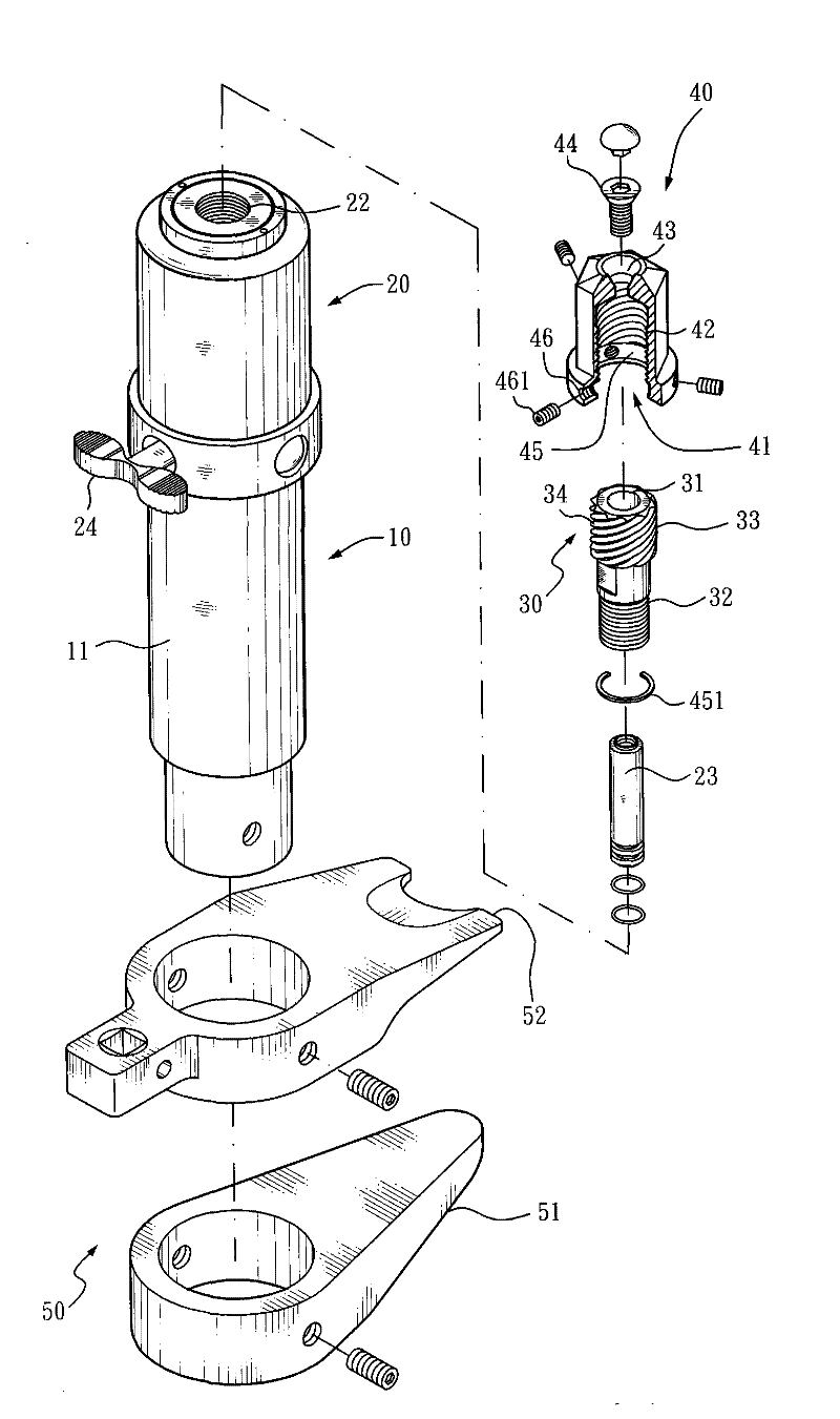
[0033] like Figure 2 to Figure 7 As shown in the drawings, a reciprocating hydraulic system of the present invention mainly includes:

[0034] A hydraulic output device 10 includes a hydraulic cylinder 11, and an output shaft 12 is arranged in the hydraulic cylinder 11, and the hydraulic cylinder 11 can drive the output shaft 12 to protrude from the hydraulic cylinder 11 by the input liquid pressure.

[0035] A hydraulic input device 20, which is a common hydraulic or oil pressure generating device, includes an oil storage tank for storing liquids such as hydraulic water or oil and a hydraulic pump (not shown), the oil storage tank is used The pipeline communicates with the hydraulic cylinder 11 through the hydraulic pump, wherein the hydraulic pump has an input shaft 23 exposed on the surface of the hydraulic input device 20, and the input shaft 23 can drive the hydraulic pump to move from the oil storage tank. The hydraulic pressure is sent to the hydraulic cylinder 11 and...


PUM


Abstract

The invention discloses a reciprocating hydraulic system, which mainly comprises a hydraulic output device and a hydraulic input device, wherein the hydraulic output device comprises a hydraulic cylinder with an output shaft; the hydraulic input device is provided with an input shaft exposed on the surface; the input shaft can drive the hydraulic input device to generate a hydraulic pressure and convey the hydraulic pressure to the hydraulic cylinder and the output shaft; the input shaft of the hydraulic input device is sleeved with a rotating seat; a driving nut is screwed on the rotating seat; and one end of the driving nut is fixedly jointed with a shaft end of the input shaft. Therefore, when the driving nut rotates on the rotating seat in a reciprocating mode, the input shaft can be driven to perform axial displacement, and the hydraulic input device is driven to generate the hydraulic pressure so as to move the output shaft.

Description

technical field [0001] The present invention is related to the hydraulic drive system of hydraulic tools, more specifically, it refers to a reciprocating hydraulic system that drives the hydraulic pressure quickly by driving the reciprocating rotation of the nut and the rotary seat. Background technique [0002] Commonly used tools often use hydraulic pressure as the driving power source, especially for tools that require large output power, such as hydraulic or oil pressure tools such as pullers and flange separators, such as figure 1 A conventional hydraulic tool is shown, which mainly includes: [0003] A hydraulic pressure generating device 1, which is provided with an oil storage tank and a hydraulic pump (not shown in the figure), the hydraulic pump protrudes from the outer surface of the hydraulic pressure generating device 1 with an input shaft 2, and the input shaft 2 shaft end There is a pressing rod 3, and the shaft end of the pressing rod 3 is connected with the...

Claims


Application Information

Patent Timeline
IPC IPC(8): F15B15/14F15B15/20
CPCB25B27/026B25B27/304F15B7/00F15B7/005
Inventor 陈钰霖
Owner 陈钰霖
Features
  • R&D
  • Intellectual Property
  • Life Sciences
  • Materials
  • Tech Scout
  • Unparalleled Data Quality
  • Higher Quality Content
  • 60% Fewer Hallucinations
Learn More