
Data transmission method and device

A data transmission method and a specific data technology, which are applied in the field of data transmission methods and devices, can solve problems such as lowering system efficiency, inability to transmit data, and high signaling overhead, so as to improve system efficiency, simplify data transmission processes, and reduce signaling. cost effect

Inactive Publication Date:
View PDF3 Cites 79 Cited by
  • Summary
  • Abstract
  • Description
  • Claims
  • Application Information

AI Technical Summary

Problems solved by technology

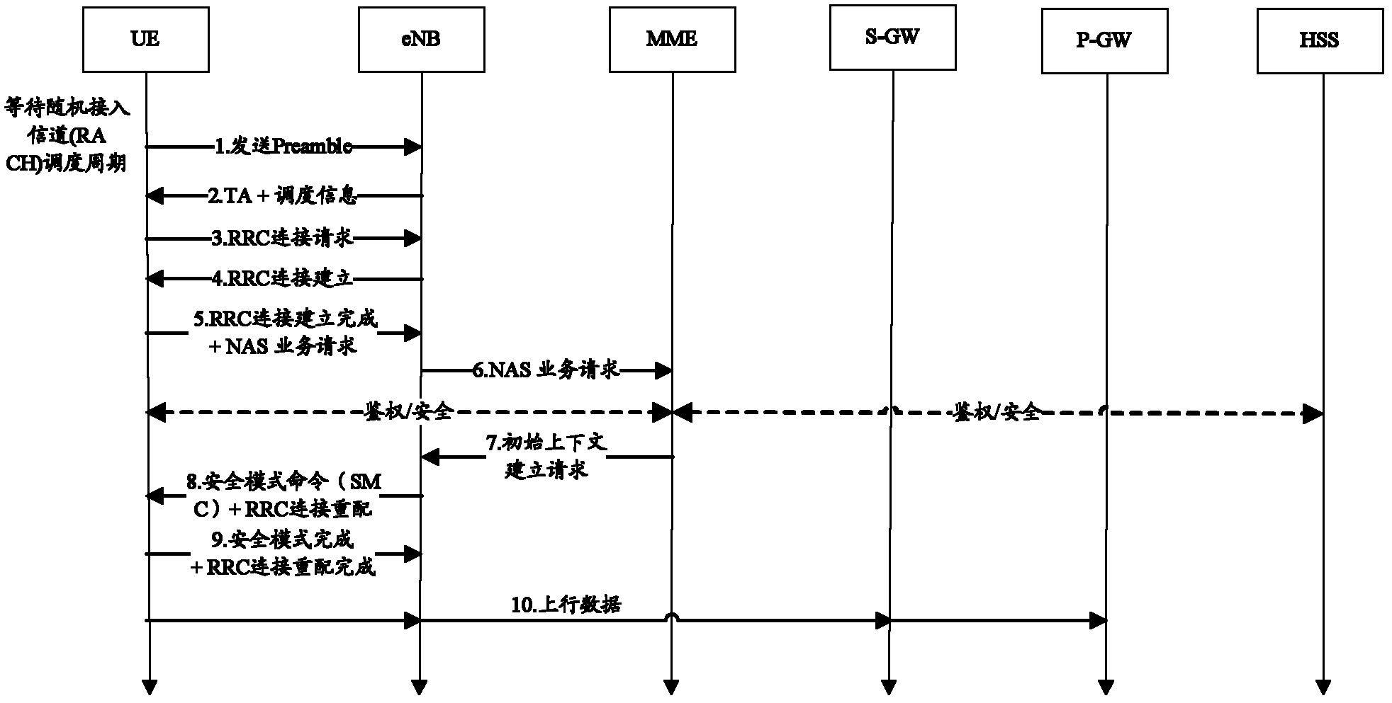
However, in order to send these data, the network and the MTC UE also need to pass such as figure 2 In the signaling process shown, after the DRB / radio bearer (RB) and the S1 / Iu interface bearer are established, data can be transmitted between the UE and the network side through the DRB / RB, S1 / Iu bearer. The SRB in the prior art only Can be used to transmit signaling, but not data
Therefore, the signaling overhead required to transmit data with a small amount of data will be relatively large, seriously reducing system efficiency

Method used


Image

  • Data transmission method and device
  • Data transmission method and device
  • Data transmission method and device

Examples


Embodiment 1

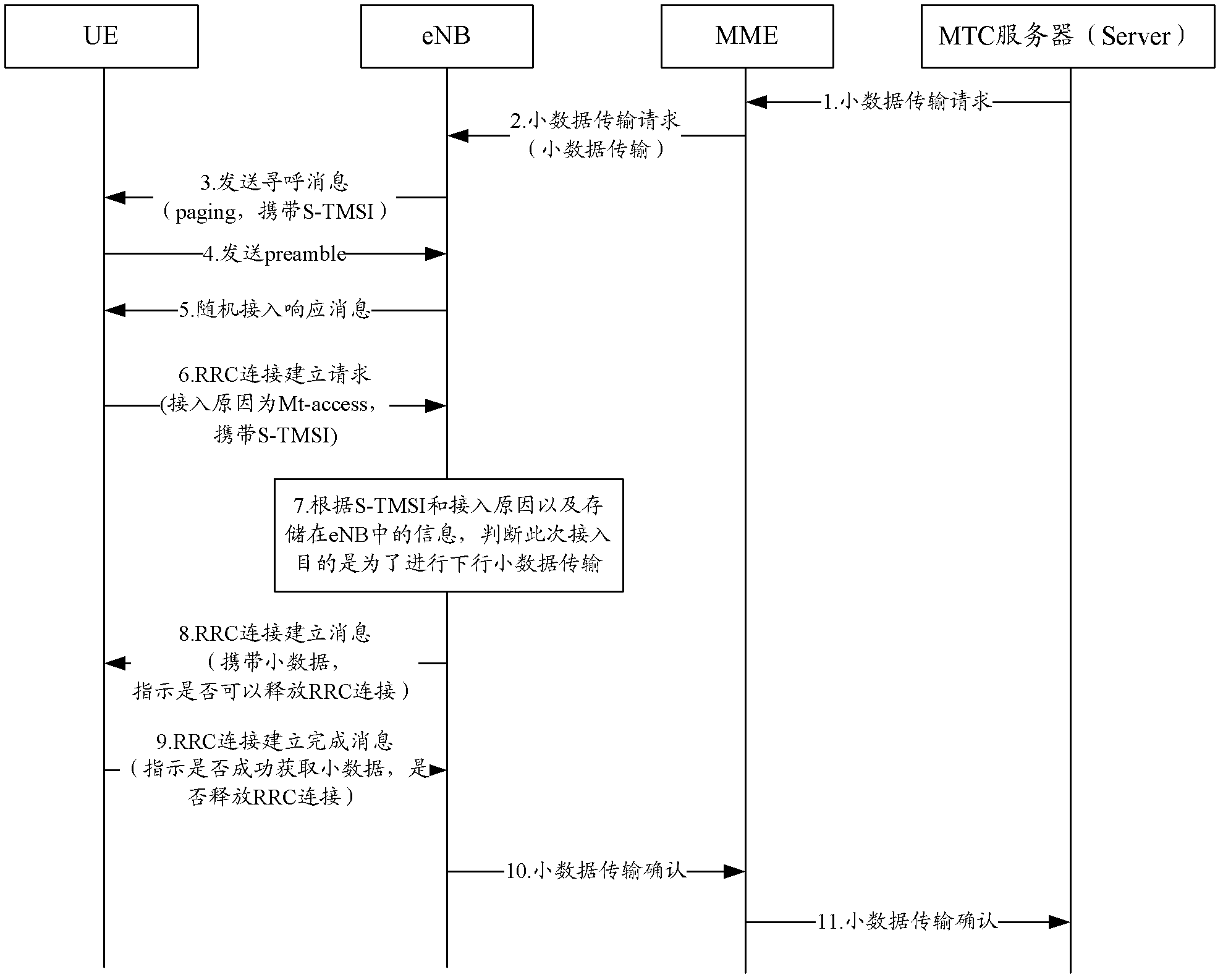
[0138] and image 3 The process shown is similar. After receiving the RRC connection establishment message, the UE forwards the NAS container in it to the NAS layer, and obtains the indication information whether the small data is successfully obtained from the NAS layer. If the small data is obtained correctly, follow the Image 6 process shown.

Embodiment 2

[0140] and image 3 The flow shown is similar. After receiving the RRC connection establishment message, the UE forwards the NAS container in it to the NAS layer, and obtains the indication information whether the small data is successfully obtained from the NAS layer. If the small data is not successfully obtained, follow the Figure 7 process shown.

Embodiment 3

[0142] and image 3 The flow shown is similar. After receiving the RRC connection establishment message, the UE forwards the NAS container in it to the NAS layer, and obtains the indication information whether the small data is successfully obtained from the NAS layer. If the small data is correctly obtained, and it is determined NAS also needs to initiate a new service request, then follow the Figure 8 process shown.

[0143] Wherein, the base station does not release the RRC connection, but continues to forward the service request (service request) message to the MME, and executes subsequent procedures according to existing regulations.


PUM


Abstract

The invention discloses a data transmission method and a device for reducing signaling expense needed by data transmission with low data volume, simplifying the data transmission flows and improving the system efficiency. The data transmission method comprises the following steps: a base station receives a specific data transmission request from a core network to obtain specific data and an identifier of user equipment (UE) needing to receive the specific data; the base station carries out paging to the UE according to the identifier of the UE, and after receiving a paging response replied by the UE, the base station transmits the specific data to the UE according to the signaling radio bearer (SRB).

Description

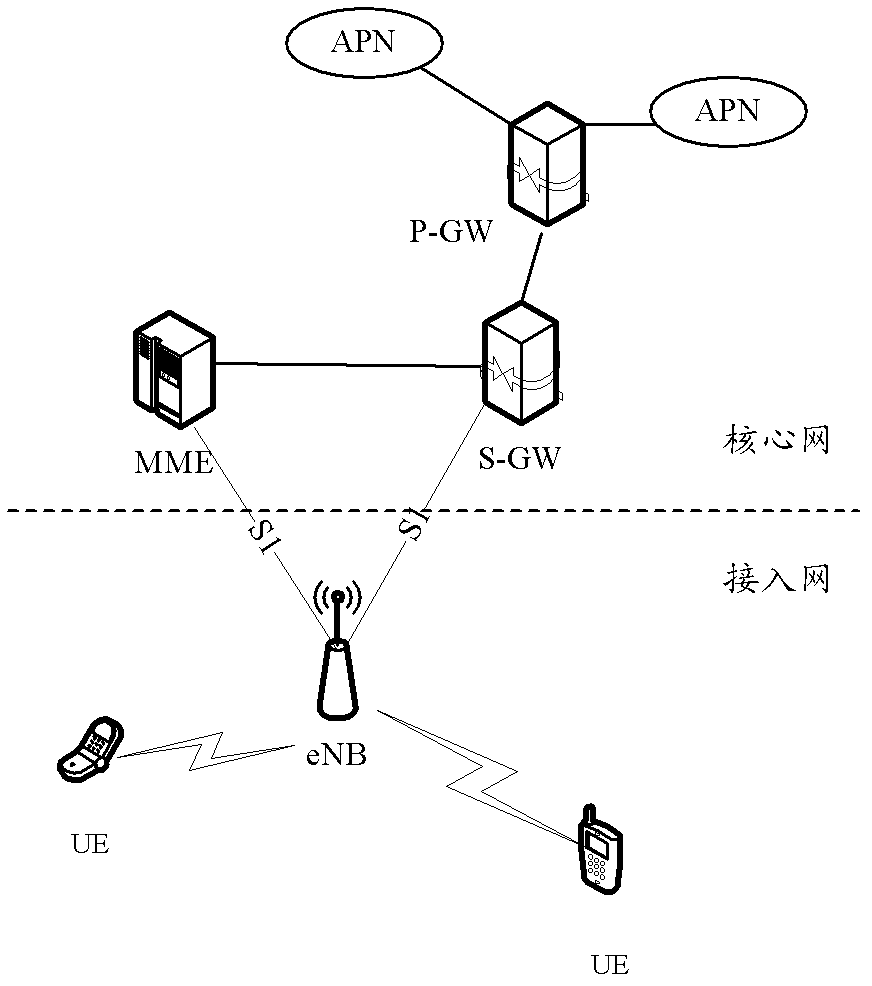
technical field [0001] The present invention relates to the field of communication technology, in particular to a data transmission method and device. Background technique [0002] Long Term Evolution (LTE) system network architecture such as figure 1 As shown, in order to facilitate the development of new services, the LTE system adopts the design method of separating the user plane and the control plane. Serving Gateway (S-GW) is responsible. The main functions of MME are non-access stratum (Non Access Stratum, NAS) signaling establishment, NAS signaling security, cross-core network signaling establishment, tracking service when LIE is in idle mode, roaming service, authorization and bearer management etc. S-GW is the gateway point for eNB switching, forwarding 2G / 3G and other system services, and completes buffering of downlink packets, some initialization work, specified interception, packet routing and forwarding, etc. The P-GW is used for policy enforcement, packet...

Claims


Application Information

Patent Timeline
Patent Type & Authority Applications(China)
IPC IPC(8): H04W68/00
CPCH04W72/04H04W68/00H04W76/10H04W76/30
Inventor 全海洋陈东
Learn More