Electromechanical compound transmission device of tracked vehicle

A technology of electromechanical composite transmission and transmission device, which is applied in the direction of power device, pneumatic power device, vehicle components, etc., can solve the problems of reducing the overall size of the transmission device and high requirements for traction motors, so as to achieve full utilization of system power and reduce research and development. Difficulty, small overall size effect

Active Publication Date: 2011-11-02
CHINA NORTH VEHICLE RES INST
View PDF8 Cites 40 Cited by
  • Summary
  • Abstract
  • Description
  • Claims
  • Application Information

AI Technical Summary

Problems solved by technology

[0007] The purpose of the present invention is to provide an electromechanical compound transmission device for tracked vehicles. The present invention provides a new type of double-sided drive from the perspectives of excessive requirements on the motor caused by the steering cycle power of the tracked vehicle and making full use of the system power. The tracked vehicle electromechanical compound transmission

Method used


Image

  • Electromechanical compound transmission device of tracked vehicle
  • Electromechanical compound transmission device of tracked vehicle
  • Electromechanical compound transmission device of tracked vehicle

Examples


Embodiment 1

[0041] Example 1: climbing

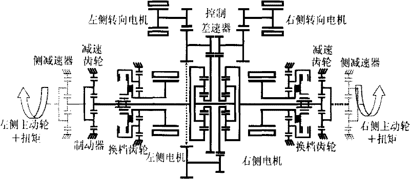
[0042] The brakes 10 and 18 are closed, the clutches 3 and 7 are disconnected, and the transmission mechanisms on the left and right sides are in the first gear state; the power is converted into electric energy by the engine 13 through the generator 15 and then transmitted to the power control unit 16, through the frequency conversion controller 11 on the left Control the left side motor 6 and the right side motor 4 frequency conversion controllers (11,17) with the right frequency conversion controller 17 and control the left and right side motors (4,6) to rotate at the same speed in the same direction, driving the vehicle to climb a slope.

Embodiment 2

[0043] Example 2: Normal driving

[0044] The brakes 10 and 18 are disconnected, the clutches 3 and 7 are closed, and the speed change mechanism on the left and right sides is in the second gear state; the power is converted into electric energy by the engine 13 through the generator 15 and then transmitted to the power control unit 16, through the left and right frequency conversion controllers ( 11,17) control the left and right side motors (4,6) to rotate in the same direction and at the same speed to drive the vehicle to run normally.

Embodiment 3

[0045] Example 3: Center Steering

[0046] The brakes 10 and 18 are closed, the clutches 3 and 7 are disconnected, and the transmission mechanisms on the left and right sides are in the first gear state; the power is converted into electric energy by the engine 13 through the generator 15 and then transmitted to the power control unit 16, through the frequency conversion controller 11 on the left And the right frequency conversion controller 17 controls the left motor 6 and the right motor 4 to rotate at the same speed in the opposite direction, so as to realize the center steering of the vehicle.


PUM


Abstract

The invention relates to an electromechanical compound transmission device of a tracked vehicle and belongs to the field of arrangement or installation of automobile transmission devices. The transmission device is composed of two motors, a planetary gear shift mechanism and a power coupling mechanism; when the tracked vehicle runs straight, the transmission device provided by the invention controls the two motors to be at the same speed; and when the tracked vehicle changes the direction, one part of overturning circulation power at the inner side is recycled as electric power and transmitted to the motor at the outer side by taking the motor at the inner side as a power generator, one part of the overturning circulation power is output to an outside tracked belt through a power coupling mechanism in a mechanical mode, and the power driving requirement of the motor at the outer side is reduced. Through the transmission device provided by the invention, the high requirements for the motors by a double-side motor individual driving type are reduced, the system power waste for the horizontal-axis zero speed difference electromechanical compound driving type is avoided, the overturning system with double-flow transmission for the traditional tracked belt is saved, thus the system efficiency is utilized fully, the device has the advantages of flexible arrangement, small general size and the like, and the device is extremely suitable for high-power tracked vehicles.

Description

technical field [0001] The invention belongs to the field of arrangement or installation of vehicle transmissions, and in particular relates to an electromechanical compound transmission for crawler vehicles. Background technique [0002] The domestic and foreign researches on the electric transmission of tracked vehicles mainly focus on the double-sided motor independent drive type and the electromechanical compound drive type with horizontal axis and zero differential speed. [0003] Such as figure 1 It is a double-sided motor independent drive type, and the structure of the double-sided motor independent drive type is relatively simple, and the two drive motors are independently controlled. When driving in a straight line, it is realized by driving the left and right driving wheels by the main motor, and the two motors must be controlled at the same speed; when turning, it is realized by controlling the speed difference generated by the left and right traction motors, be...

Claims


Application Information

Patent Timeline
IPC IPC(8): B60K6/36
Inventor 盖江涛李慎龙周广明马晓枫马田李洪武
Owner CHINA NORTH VEHICLE RES INST
Why Eureka
Try Eureka