Rotating shaft sealing structure

A rotating shaft seal and rotating shaft technology, which is applied in the direction of engine seals, engine components, mechanical equipment, etc., can solve the problems of large resistance, easy wear of the inner edge surface of the seal, and complicated maintenance process, so as to reduce the rotation resistance and use cost Low, maintain the effect of smooth rotation

Inactive Publication Date: 2011-11-02
合肥恒信动力科技股份有限公司
View PDF6 Cites 1 Cited by
  • Summary
  • Abstract
  • Description
  • Claims
  • Application Information

AI Technical Summary

Problems solved by technology

The problem with this sealing structure is that the rotating shaft is tightly bound by the inner surface of the seal, and the resistance is relatively large when rotating, and the inner surface of the seal is easy to wear. Once the wear occurs, the reliability of the seal can only be guaranteed by replacing the seal. , its maintenance process is complex

Method used


Image

  • Rotating shaft sealing structure
  • Rotating shaft sealing structure
  • Rotating shaft sealing structure

Examples


Embodiment Construction

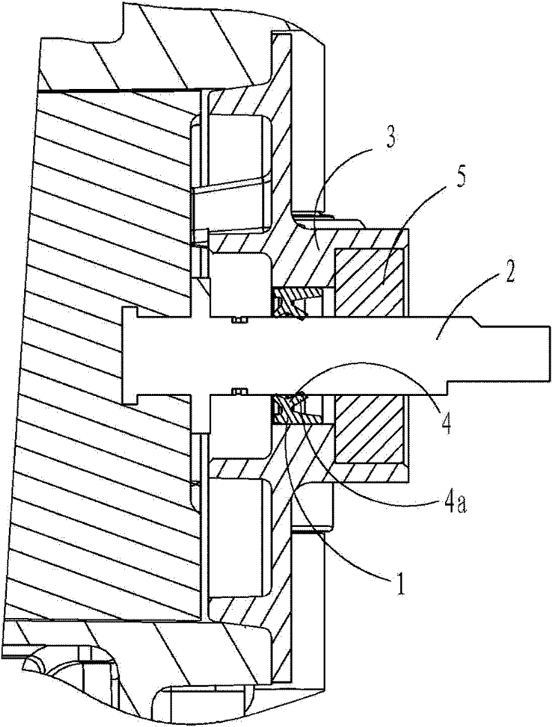
[0013] see figure 1 , the rotating shaft sealing structure in this embodiment is that the annular seal 1 is set between the inner hole of the rotating shaft 2 and the end cover 3, the rotating shaft 2 is positioned in the inner hole of the end cover 3 through the bearing 5, and the outer surface of the sealing member 1 The inner edge of the sealing member 1 is closely matched with the inner hole wall of the end cover 3, and the inner edge of the sealing member 1 is in conflict with the cylindrical surface of the rotating shaft 2 to prevent air leakage.

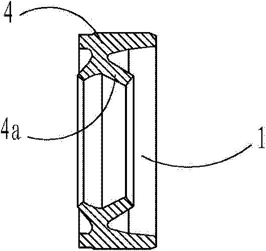
[0014] figure 1 , figure 2 As shown, in this embodiment, the cross-section of the sealing member 1 is set in a “K” shape, with one side of the flat surface of the “K”-shaped cross-section as the outer edge of the sealing member 1, and the other side of the “K”-shaped cross-section A pair of inclined-plane flanges 4 with a "eight" character on the sides is the inner edge of the sealing member 1, and the pair of inclined-plan...


PUM


Abstract

The invention discloses a rotating shaft sealing structure. A circular sealing element is sleeved between a rotating shaft and an inner hole of an end cover, the outer edge of the sealing element is tightly matched with the wall of the inner hole of the end cover, and the inner edge of the sealing element is butted against the cylindrical surface of the rotating shaft. The rotating shaft sealing structure is characterized in that the cross section of the sealing element is of a 'K' shape, the flat surface side of the K-shaped cross section is the outer edge of the sealing element, and one pair of splay inclined surface flanges at the other side on the K-shaped cross section are inner edges of the sealing element. The sealing structure provided by the invention has the function of automatic compensation, pressing force forming sealing mainly comes from the elasticity of the flange and outside pressure, the pressing force is small, and abrasion is small. The resistance to the rotating shaft in rotation can be effectively reduced, and the replacement frequency of the sealing element is reduced.

Description

technical field [0001] The invention relates to a sealing structure, more specifically to a sealing structure of a rotating shaft. Background technique [0002] In the prior art, the sealing structure of the rotating shaft is to install a sealing ring between the rotating shaft and the inner hole of the end cover. The sealing ring is a columnar body, which is a rubber seal with a metal skeleton in the center. The inner and outer edges of the sealing ring are both The flat surface, the outer edge of the sealing ring and the inner hole of the end cover maintain an interference fit, and this method is used to block the leakage along the air along the rotating shaft and achieve the purpose of sealing. The problem with this sealing structure is that the rotating shaft is tightly bound by the inner surface of the seal, and the resistance is relatively large when rotating, and the inner surface of the seal is easy to wear. Once the wear occurs, the reliability of the seal can only ...

Claims


Application Information

Patent Timeline
Patent Type & Authority Applications(China)
IPC IPC(8): F16J15/32F16J15/3232
Inventor 陈仰帆王文杰
Owner 合肥恒信动力科技股份有限公司
Why Eureka
Try Eureka