Self-compensating ball valve structure for seal wear

An automatic compensation and ball valve technology, applied in the direction of valve housing structure, shaft seal, valve details, etc., can solve the problems of valve leakage, short valve life, valve seat wear under pressure, etc., to achieve good compensation for valve seat wear and prolong life Effect

Inactive Publication Date: 2014-06-11
SUZHOU KEDI FLUID CONTROL EQUIP
View PDF5 Cites 0 Cited by
  • Summary
  • Abstract
  • Description
  • Claims
  • Application Information

AI Technical Summary

Problems solved by technology

At present, the material of the valve seat of the existing ball valve is polytetrafluoroethylene (PTFE). The valve seat and the ball are in surface-to-surface contact. Will lead to valve leakage, resulting in a relatively short life of the valve

Method used


Image

  • Self-compensating ball valve structure for seal wear
  • Self-compensating ball valve structure for seal wear

Examples


Embodiment 1

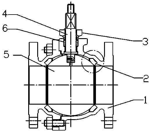
[0016] In order to save money conveniently when the ball 5 or the valve stem 4 is damaged and needs to be replaced, the ball 5 and the valve stem 4 are detachably connected.

[0017] A sealing packing 6 is provided at the lower end of the bonnet 3, the junction of the valve stem 4 and the valve body 1 to ensure the sealing of the upper part of the valve, so that the overall sealing performance of the valve is better. The material of the sealing packing is PTFE, which has good elasticity and has Very good sealing performance.

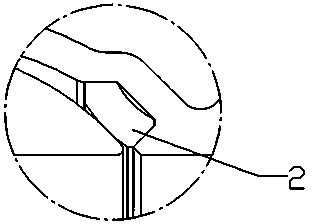
[0018] Valve seat 2 is made of PTFE material through special process, which has long-term plastic and elastic deformation. The surface of PTFE material has outstanding self-lubricating property, and almost all viscous substances cannot adhere to its surface; the valve body (1) Unique I-shaped design, after the ball 5 is assembled on the valve body 1, the compressed valve seat 2 enters the four corners of the I-shaped structure, and the valve seat 2 has g...


PUM


Abstract

The invention relates to a ball valve structure, in particular to a self-compensating ball valve structure for seal wear. The self-compensating ball valve structure comprises a valve body, a valve seat, a valve cover, a valve rod and a ball body, wherein the ball body is located inside the valve body, the valve rod is fixed at the upper end of the ball body, the valve cover is fixed at the upper end of the valve rod and the valve seat is arranged between the inner part of the valve body and the ball body. The valve body is of an I-shaped structure; preferably, in order to save the cost when either the ball body or the valve rod is needed to change due to destroy, the valve body and the valve rod are movably connected; more preferably, a sealing filler is arranged on a connection among the lower end of the valve rod, the valve rod and the valve body. According to the ball valve structure, the unique I-shaped design is adopted for the valve body, so that the seal of the valve seat has a self-compensating function, the function of well compensating the wear of the valve seat can be reached, and the life of the ball valve can be prolonged.

Description

technical field [0001] The invention relates to a ball valve structure, in particular to a ball valve structure with automatic sealing wear compensation. Background technique [0002] The ball valve is mainly used to cut off and conduct the medium in the pipeline. Since the flow area of ​​the ball valve is consistent with the inner hole of the pipeline after the ball valve is opened, the resistance is very small and there is basically no pressure loss. Therefore, it is widely used in petroleum, chemical, medical, metallurgy, Mining, food and many other fields. If it cooperates with the regulating actuator, it can also regulate the flow and pressure of the medium in the pipeline. At present, the material of the valve seat of the existing ball valve is polytetrafluoroethylene (PTFE). The valve seat and the ball are in surface-to-surface contact. It will lead to leakage of the valve, resulting in a relatively short service life of the valve. Contents of the invention [00...

Claims


Application Information

Patent Timeline
Patent Type & Authority Applications(China)
IPC IPC(8): F16K27/06F16K41/02F16K5/20F16K5/08
CPCF16K27/067F16K5/0626F16K5/0668F16K5/0694F16K5/08
Inventor 田洪卫
Owner SUZHOU KEDI FLUID CONTROL EQUIP
Why Eureka
Try Eureka