Two-way non-reverse overrunning clutch

An overrunning clutch and non-return stop technology, applied to one-way clutches, clutches, mechanical equipment, etc., can solve the problems of inconvenient maintenance and short service life of two-way clutches, and achieve reliable operation, improved mechanical transmission efficiency, and simple structure Effect

Active Publication Date: 2017-12-29
BEIJING UNIV OF TECH
View PDF6 Cites 0 Cited by
  • Summary
  • Abstract
  • Description
  • Claims
  • Application Information

AI Technical Summary

Problems solved by technology

[0004] In order to overcome technical problems such as the traditional overrunning clutch can only transmit in one direction, the service life of the two-way clutch is short, and the maintenance is inconvenient, the present invention provides a two-way non-reverse overrunning clutch, which can transmit torque in two directions, disengage in two directions, and It can automatically compensate the clearance of the cage, which is suitable for various working conditions

Method used


Image

  • Two-way non-reverse overrunning clutch
  • Two-way non-reverse overrunning clutch
  • Two-way non-reverse overrunning clutch

Examples


Embodiment Construction

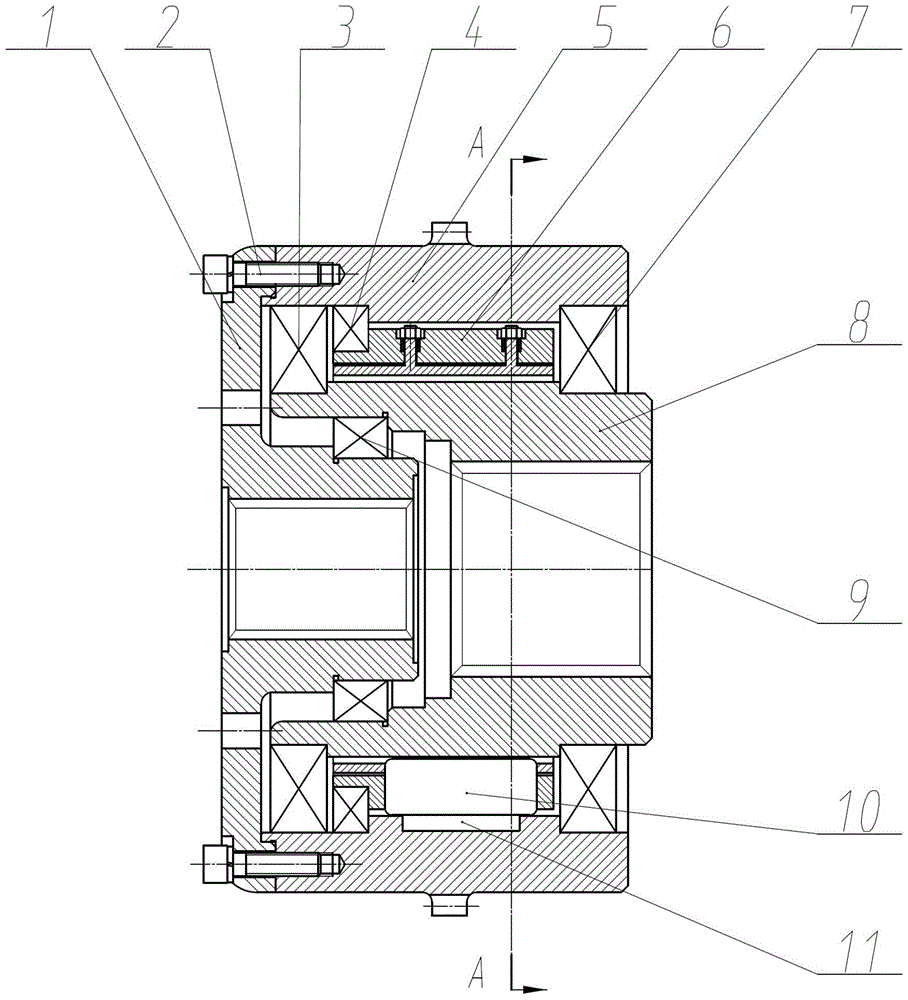
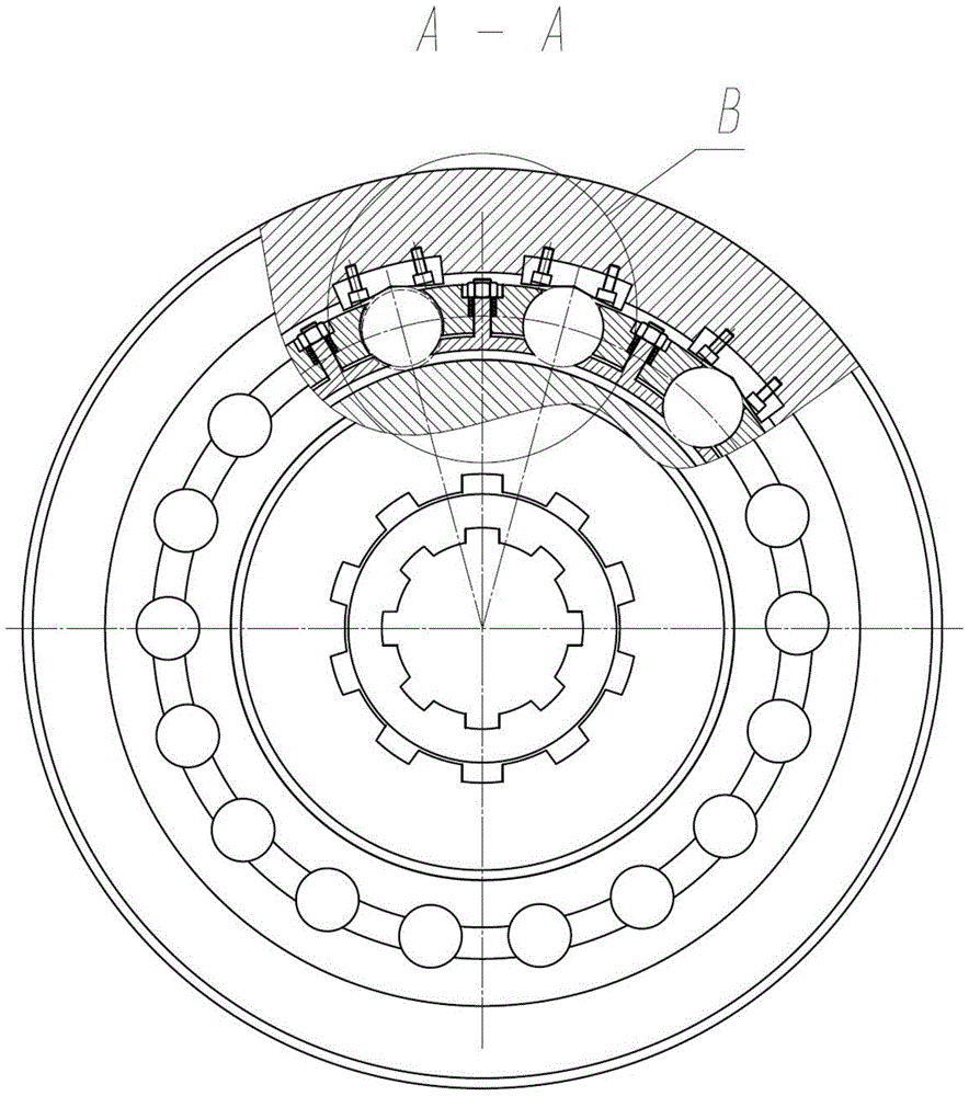
[0015] like Figure 1-3 As shown, the present invention will be further described through specific embodiments below.

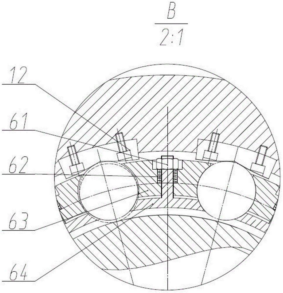
[0016] A two-way non-reverse overrunning clutch, the lower cover plate 1 of the clutch is connected with the outer race 5 through the screw a2. The wedge block 11 is fixed on the outer race 5 by the screw b12. Furthermore, the outer race 5 and the cage outer ring 63 are coupled through the ball bearing b4. The rollers 10 are set in the roller grooves of the cage assembly 6, and two small shafts with thread protrude between every two roller grooves of the inner ring 64 of the cage, and the small shafts pass through the holes of the outer ring 63 of the cage. out. A spring 62 is sheathed on the small shaft, and the force of the spring 62 is adjusted by a nut 61 , so that the cage outer ring 63 and the cage inner ring 64 are close to each other. The inner race 8 is connected with the outer race 5 through two ball bearings a3 and b7, and there is a tapered ro...


PUM


Abstract

The invention relates to a bidirectional non-backstopping overrun clutch. A retainer assembly comprises a retainer outer ring, a retainer inner ring, a spring and a nut. When power is input into a driving end, a clutch outer race, while driving a wedge block to rotate, pushes a roller to move downwards to contact with an inner race, thereby enabling the clutch outer race, the roller and the inner race to engage with each other and then allowing the clutch to transfer torque. When the driving end loses the power, the roller moves to a middle position of the wedge block and thus disengages from the inner race. Regardless of clockwise or counterclockwise rotation of the inner race serving as a driving wheel, the outer race may not be driven to rotate together, i.e., the clutch is in a bidirectional disengaged state. The bidirectional non-backstopping overrun clutch is applicable to various working conditions of a prime mover and a transmission shaft, wide in application range, and steady in engagement, reliable in working, free from noise and simple in structure, and has a great significance for improving the mechanical transfer efficiency of ship power as well as damping and noise reducing.

Description

technical field [0001] The invention belongs to a transmission device of a power device, and in particular relates to a bidirectional non-backstop overrunning clutch. It is used in the transmission shafting of the power plant of various naval ships. It is also suitable for the transmission shafting of the combined power plant of the ship. Background technique [0002] In the current field of combined power transmission of Chinese ships, the clutch is mainly used to realize the combination and disengagement of the power device and the actuator. However, when the two powers transmit power at different speeds, how to perform functions such as two-way combination and two-way separation, and how the two do not affect each other when different power devices transmit power independently. With the current existing clutch, it is difficult to realize. Currently commonly used clutches mainly have three structural forms: friction plate clutches, wedge-shaped one-way clutches, and rol...

Claims


Application Information

Patent Timeline
Patent Type & Authority Patents(China)
IPC IPC(8): F16D41/067
CPCF16D41/067
Inventor 聂松林肖述晗
Owner BEIJING UNIV OF TECH
Why Eureka
Try Eureka