
Cross type efficient reinforced braking method

A cross-type, high-efficiency technology, applied in the direction of brake actuators, gear transmission mechanisms, mechanical equipment, etc., can solve problems such as unsatisfactory effects, high pull-in voltage, large pull-in current, etc., and achieve low pull-in voltage , small pull-in current, large braking force

Inactive Publication Date: 2013-04-10
陈海水
View PDF9 Cites 0 Cited by
  • Summary
  • Abstract
  • Description
  • Claims
  • Application Information

AI Technical Summary

Problems solved by technology

[0003] At present, the brake structure in use has defects such as large pull-in current, high pull-in voltage, frequent slipping when braking, easy to lock the brake, and difficult debugging, and the effect is not satisfactory.

Method used


Image

  • Cross type efficient reinforced braking method
  • Cross type efficient reinforced braking method
  • Cross type efficient reinforced braking method

Examples


Embodiment Construction

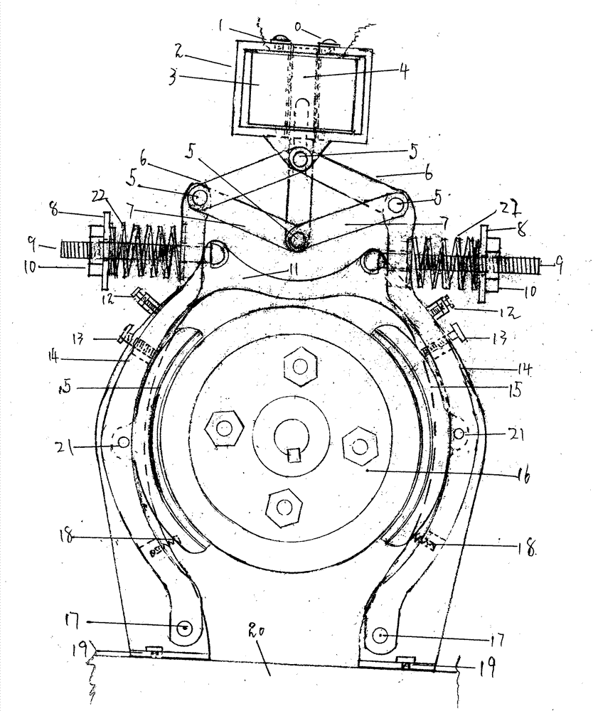
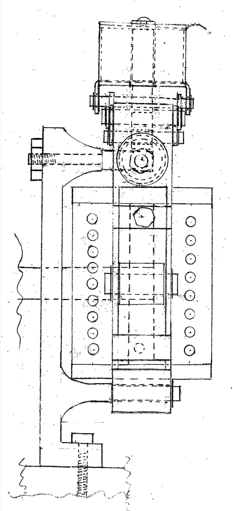
[0024] Put the connecting shaft 5 in the pair of perforations on the front and rear planes near the top of the left and right brake frames 14, and then stack the front and rear planes of the two support plates 6 so that the center points of the pair of perforations at one end of the plane are aligned before and after aligning with each other. After the connecting shaft 5 that has been put on earlier on the front and rear planes of the brake frame 14 upper ends is put on, put jump ring in the circular groove on the arc surface of the two near tops of the connecting shaft 5 .

[0025] Put the end of the round hole on the front and rear planes of the suction iron core 4 downwards, and insert the inner planes of the front and back planes and the superimposed support plate 6 that has been placed on the upper ends of the left and right brake frames 14 into its space correspondingly, so that the left side brake The other end of that piece of support plate 6 close to its plane on the m...


PUM


Abstract

The invention discloses a cross-type high-efficiency booster braking structure. The beneficial effects of the present invention are: 1. The pull-in current is small, the pull-in voltage is low, and the brake release force is large, which can form a more effective match with the integrated circuit. 2. Reliable performance, convenient debugging and relatively low production cost. 3. The braking force is large, which can more effectively prevent the brake wheel from slipping during the braking process. The components include; 1 magnetic frame, 2 suction core, 3 support plate, 4 connecting shaft, 5 right-angle bolts, 6 non-magnetic tube.

Description

technical field [0001] The invention relates to a dynamic braking structure, more specifically to a cross-type high-efficiency booster braking structure. Background technique [0002] current technology [0003] At present, the brake structure in use has defects such as large pull-in current, high pull-in voltage, frequent slipping during braking, easy to lock the brake, and difficult debugging, and the effect is not satisfactory. Contents of the invention purpose of invention [0004] The purpose of the present invention is exactly in order to overcome above-mentioned shortcoming. [0005] Beneficial effect [0006] 1. The pull-in current is small, the pull-in voltage is low, and the brake release force is large, which can form a more effective match with the integrated circuit. [0007] 2. Stable performance, convenient debugging and relatively low production cost. [0008] 3. The braking force is large, which can more effectively prevent the occurrence of slipping...

Claims


Application Information

Patent Timeline
Patent Type & Authority Patents(China)
IPC IPC(8): F16D65/22F16D121/22
Inventor 陈海水
Owner 陈海水
Learn More