
A manipulating device and an electric vehicle including the same

A control device and electric vehicle technology, applied in the field of electric vehicles, can solve problems such as unsafety, driver difficulty, wire tube winding, etc., and achieve the effects of large braking force, convenient driving, and convenient operation

Pending Publication Date: 2019-01-15
王德宇
View PDF2 Cites 0 Cited by
  • Summary
  • Abstract
  • Description
  • Claims
  • Application Information

AI Technical Summary

Problems solved by technology

[0002] Low-speed functional electric vehicles include structural column pouring small pump vehicles, electric carts, electric self-rolling vehicles, etc. These electric vehicles travel slowly and do not have a driver's seat. , brake, and speed for driving control. There are many disadvantages in the existing driving device. For example, an electric cart proposed in Patent No. 201520842271.1 and an electric cart proposed in Patent No. The speed and driving direction of the cart can be braked by pressing down the direction control arm or the brake steering lever. When the vehicle is reversing, when going up and down slopes or when the distance between the driver and the electric car is too close, the pressing operation is very difficult for the driver. Increased unsafe factors
[0003] Patent application number: 2017210418696 proposes a multifunctional centralized control mechanism, which can control the direction, speed, forward and reverse of the vehicle, and apply push or pull force to the operating handle in the opposite direction of driving to realize the braking function, which is convenient to operate, but The main sheave of the centralized control device needs to rotate when turning, and the pull rope and lead wire tube will swing with the rotation of the main sheave, causing the wire tube to be entangled and worn. In addition, the two pull ropes c and a are connected to a brake at the same time. Parts, such as electric three-four-wheel carts need more pull ropes when braking more than two wheels, and swing with the rotation of the main pulley, which is not beautiful, has a higher failure rate, and is unreasonable in layout

Method used


Image

  • A manipulating device and an electric vehicle including the same
  • A manipulating device and an electric vehicle including the same
  • A manipulating device and an electric vehicle including the same

Examples


Embodiment Construction

[0021] The technical characteristics of the present invention will be described in detail below in conjunction with the accompanying drawings.

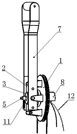
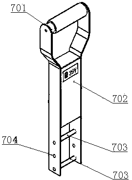
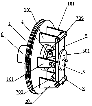
[0022] Such as figure 1 , figure 2 , image 3 and Figure 4 As shown, a control device includes a steering frame 1, a pendulum block 2, a bump 3, a fixed block 4, a guide shaft 5, a positioning shaft 6, a handle 7, a central tube 8 and a brake cable 12. The steering frame 1 There is a hole in the center, and a center pipe 8 is installed in the hole. One end of the center pipe 8 is provided with a thread, and the other end is connected with the frame of the electric vehicle. The direction frame 1 is hinged with one end of the two pendulum blocks 2. , the concaves of the two pendulum blocks 2 are opposite to each other, and there is a bump 3 between the two pendulum blocks 2, and a pull wire hole 301 is arranged on the bump 3, and a fixed block 4 is arranged in the central tube 8, and the fixed block 4 is provided with a number of ...


PUM


Abstract

The invention relates to the field of manipulating devices, and discloses a manipulating device and an electric vehicle including the manipulating device. The manipulating device includes a bogie, a pendulum block, a lug, a fixed block, a guide shaft, a positioning shaft, a handle, a center pipe and a brake cable. Braking can be achieved by pushing or pulling the handle in the opposite direction when the driver is moving forward or backward. The brake force is great and the operation is convenient. When steering, the brake cable does not swing with the turning of the steering frame. The deviceis safe and reliable. The parking is opened or closed by rotating the parking knob. The layout is reasonable and the driving is convenient.

Description

technical field [0001] The invention relates to a control device, more specifically, to a control device and an electric vehicle containing the control device. Background technique [0002] Low-speed functional electric vehicles include structural column pouring small pump vehicles, electric carts, electric self-rolling vehicles, etc. These electric vehicles travel slowly and do not have a driver's seat. , brake, and speed for driving control. There are many disadvantages in the existing driving device. For example, an electric cart proposed in Patent No. 201520842271.1 and an electric cart proposed in Patent No. The speed and driving direction of the cart can be braked by pressing down the direction control arm or the brake steering lever. When the vehicle is reversing, when going up and down slopes or when the distance between the driver and the electric car is too close, the pressing operation is very difficult for the driver. Unsafe factors have been added. [0003] Pa...

Claims


Application Information

Patent Timeline
Patent Type & Authority Applications(China)
IPC IPC(8): B62B5/04
CPCB62B5/0442
Inventor 王德宇
Owner 王德宇
Learn More