Wireless device testing method based on wireless ad hoc network

A wireless ad hoc network and wireless equipment technology, applied in the field of product and wireless communication, can solve the problems of short delivery cycle and can not meet the production volume, and achieve the effect of broad application value and saving time and manpower

Active Publication Date: 2011-11-09
无锡感知金服物联网科技有限公司
1 Cites 19 Cited by

AI-Extracted Technical Summary

Problems solved by technology

However, with the increasing output of wireless devices, traditional testing methods ca...

Abstract

The invention discloses a wireless device testing method based on a wireless ad hoc network. In the method, a test controller, a detecting wireless device connected with the test controller and a plurality of wireless devices to be detected are comprised in an applied hardware environment, wherein the wireless devices to be detected are respectively connected with the detecting wireless device; the test controller is used for controlling the detecting wireless device to broadcast a network grouping message to all the wireless devices to be detected; the detecting wireless device is used for allocating time slots for the wireless devices to be detected, which receive the network grouping message and then reply response messages, and testing the performances of the wireless devices to be detected in respective allocated time slots; after testing, the detecting wireless device reports the performance testing result information of all the wireless devices to be detected to the test controller; and the test controller displays the received performance testing result information. By using the wireless device testing method disclosed by the invention, the product testing speed and efficiency are greatly improved, and a large amount of time cost and manpower cost are greatly saved.

Application Domain

Technology Topic

Real-time computingProduct testing +3

Image

  • Wireless device testing method based on wireless ad hoc network
  • Wireless device testing method based on wireless ad hoc network

Examples

  • Experimental program(1)

Example Embodiment

[0024] Some embodiments of the invention are described in detail below. However, the invention can also be widely practiced in other embodiments than these embodiments, and the scope of the invention should not be limited by them, but should be determined by the appended claims.
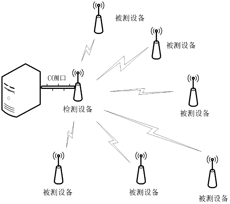
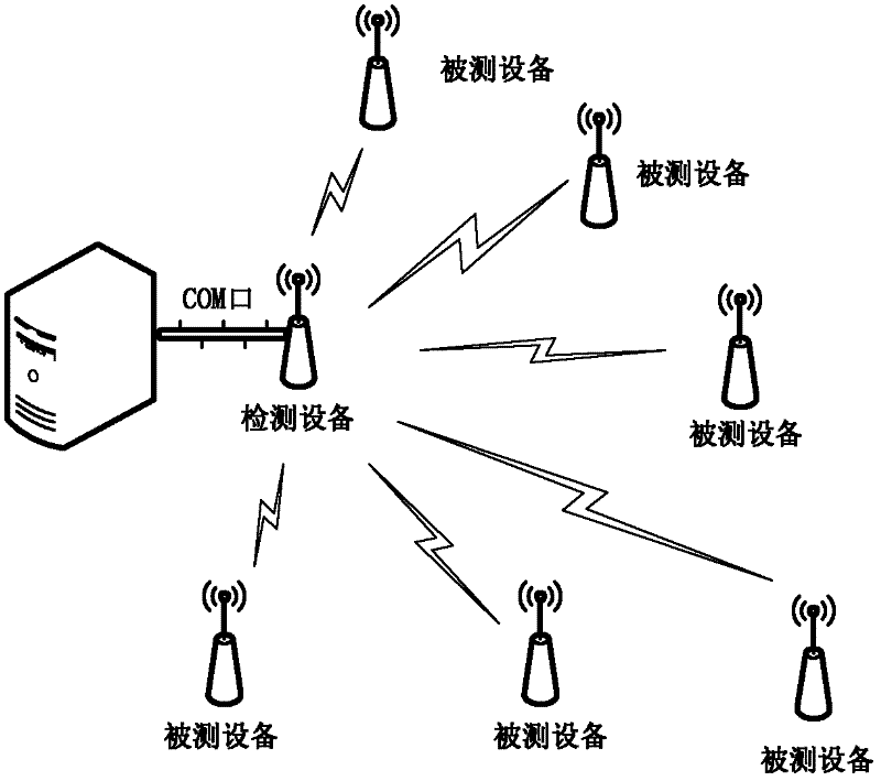
[0025] figure 1 It is a schematic diagram showing the wireless device batch test solution described in the present invention, including some basic equipment and connection methods described in the present invention. The equipment involved in the test includes a PC, a detection device, and several wireless devices to be tested. Before the wireless device under test enters the test process, if the device itself does not have an ID, it is necessary to pre-configure the ID of each device in the firmware. . The testing equipment should be the same type of equipment that does not need to be tested and has the same or similar performance as the tested equipment. The testing equipment should have a serial port or a general interface that can interact with a PC. This solution uses a serial port as an example. Then enter the testing process.
[0026] 1) Connect the testing device to the PC through the serial port, place a number of tested wireless devices that have been configured with IDs around the testing device, and use the test software running on the PC or directly use the PC serial port debugging assistant to issue a command to start the test ;
[0027] 2) When the PC issues the start test command and the detection device receives the start test command, the detection device will broadcast an ad hoc networking frame to all the tested devices through the wireless module, and the tested device receives the network frame The response message will be replied in CSMA-CA mode. In order to solve the packet loss problem, the process will use a three-way handshake mechanism until the interaction is successful or the maximum number of times that cannot be tolerated is reached. Since the wireless performance of the test equipment and the equipment under test is the same, if the performance of the equipment under test is good, the above process should be completed, and finally a star-shaped wireless ad hoc network is formed. If the test item includes a self-test performance test, the result of the self-test performance test should also be included in the response message during the networking process;
[0028] 3) The detection device allocates a time slot for the device under test that replies to the response message. The standard of the time slot length is n*t (n>=2), and t represents the time length for a complete test. The detection device starts slot scheduling at the same time;
[0029] 4) The detection device and each device under test will conduct a wireless transmission and reception performance test in the corresponding time slot, generally including the wireless signal strength test, loss Packet rate test, bit error rate test, etc. If a test result can be obtained in the testing device, it will be generated directly by the testing device; if a test result is obtained in the device under test, the device under test will send the test result in the form of wireless frames after the test Report to the test node;
[0030] 5) After the test is completed, the testing equipment will report to the PC the results of the self-test performance test of each tested equipment and the wireless transmission and reception performance results of the tested equipment obtained in the time slot communication between the testing equipment and the tested equipment;
[0031] 6) Finally, the software running on the PC will receive the data and reflect the result in the form of text or image.
[0032] It should be noted that because wireless communication has relatively high requirements on the environment, the wireless performance of wireless devices in different environments is not completely the same. For example, the wireless performance of devices in open areas is better, but the wireless performance environment in areas with severe occlusion such as laboratories is generally poor. Therefore, for different test environments, the requirements for test results are also different. So there are two possible options:
[0033] (1) On the PC, only the data results are given without giving the final judgment result (the tested equipment is good or bad);
[0034] (2) Give the final judgment result, but provide the dynamic setting of the test standard.
[0035] Due to the inherent uncertain characteristics of the self-organizing network itself, a single test failure does not completely mean that the equipment is unqualified. Or if it fails more than two times, it is determined that the equipment is unqualified and enters the repair, rework or elimination process.
[0036] The description and application of the present invention herein is illustrative, and is not intended to limit the scope of the present invention to the above-described embodiments. Variations and variations of the embodiments disclosed herein are possible, and alternative and equivalent various components of the embodiments are known to those of ordinary skill in the art. It should be clear to those skilled in the art that the present invention can be realized in other forms, structures, arrangements, proportions, and with other elements, materials and components without departing from the spirit or essential characteristics of the present invention.

PUM

no PUM

Description & Claims & Application Information

We can also present the details of the Description, Claims and Application information to help users get a comprehensive understanding of the technical details of the patent, such as background art, summary of invention, brief description of drawings, description of embodiments, and other original content. On the other hand, users can also determine the specific scope of protection of the technology through the list of claims; as well as understand the changes in the life cycle of the technology with the presentation of the patent timeline. Login to view more.

Similar technology patents

10kv live-line work insulating support rod

InactiveCN103606844ASave manpower and timeEnsure job safetyApparatus for overhead lines/cablesScrew jointLive-line working
Owner:STATE GRID CORP OF CHINA +1

Gene variation pathogenic grade determination method and device

InactiveCN106951730ASave manpower and timeAccurate divisionBiostatisticsProteomicsMonogenic inheritanceDecision-making
Owner:为朔医学数据科技(北京)有限公司

Classification and recommendation of technical efficacy words

  • Save manpower and time
  • Great application value

Leather cutting machine

ActiveCN101586171AAccelerateSave manpower and timeLeather clicking/perforating/clickingComputer engineeringPunching
Owner:DONGGUAN EMMA CNC TECH CO LTD

Multifunctional power distribution terminal integrated test system and operating method thereof

ActiveCN105785199AGreat application valueElectrical testingCombined testMonitor unit
Owner:STATE GRID FUJIAN ELECTRIC POWER CO LTD +3

Method and device for welding tube type heat exchanger by using laser scanning

InactiveCN101590570AIncreased heat exchange area and heat transfer efficiencyGreat application valueLaser beam welding apparatusTubular articlesHigh power lasersContact type
Owner:SHANGHAI INST OF LASER TECH
Why Eureka
Try Eureka