
Method for performing chemically mechanical polishing by using chemically mechanical polishing equipment

A chemical machinery, polishing machine technology, applied in electrical components, semiconductor/solid-state device manufacturing, circuits, etc., can solve the problems of low production efficiency of polishing equipment, long transmission time, large transmission distance between wafers, etc., to achieve wafer transmission. The effect of short time, high work efficiency and short wafer transfer distance

Active Publication Date: 2011-11-16
HWATSING TECH
View PDF5 Cites 19 Cited by
  • Summary
  • Abstract
  • Description
  • Claims
  • Application Information

AI Technical Summary

Problems solved by technology

However, the polishing equipment with single-disc and single-head linear structure has low production efficiency, large transmission distance between wafers, and long transmission time

Method used


Image

  • Method for performing chemically mechanical polishing by using chemically mechanical polishing equipment
  • Method for performing chemically mechanical polishing by using chemically mechanical polishing equipment
  • Method for performing chemically mechanical polishing by using chemically mechanical polishing equipment

Examples


Embodiment Construction

[0032] Embodiments of the present invention are described in detail below, examples of which are shown in the drawings, wherein the same or similar reference numerals designate the same or similar elements or elements having the same or similar functions throughout. The embodiments described below by referring to the figures are exemplary only for explaining the present invention and should not be construed as limiting the present invention.

[0033] In describing the present invention, it should be understood that the terms "longitudinal", "transverse", "upper", "lower", "front", "rear", "left", "right", "vertical", The orientation or positional relationship indicated by "horizontal", "top", "bottom", "inner", "outer", etc. are based on the orientation or positional relationship shown in the drawings, and are only for the convenience of describing the present invention and simplifying the description, rather than Nothing indicating or implying that a referenced device or elem...


PUM


Abstract

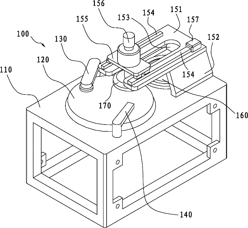
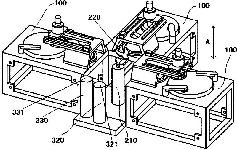
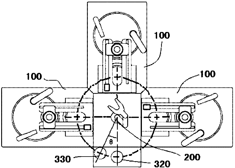
The invention discloses a method for performing chemically mechanical polishing by using chemically mechanical polishing equipment. The chemically mechanical polishing equipment comprises a plurality of chemically mechanical polishing machines, a manipulator, and transition devices, wherein the plurality of chemically mechanical polishing machines and the transition devices are arranged around the manipulator. The method comprises the following steps of: A) conveying wafers on the transition devices to at least more than one of the plurality of chemically mechanical polishing machines by the manipulator so as to polish the wafers by using the plurality of chemically mechanical polishing machines; B) conveying the polished wafers by using the manipulator to the transition devices; and C) repeating the steps A) and B) until the polishing of all wafers is finished. The method for performing chemically mechanical polishing by using the chemically mechanical polishing equipment has the advantages of short wafer transmission distance, and wafer transmission time and high working efficiency.

Description

technical field [0001] The invention relates to a method for chemical mechanical polishing using chemical mechanical polishing equipment. Background technique [0002] In the production process of large-scale integrated circuits, the requirements for the flatness of wafers are very high. At present, wafer planarization is achieved by using a chemical mechanical polishing (CMP) process, and a chemical mechanical polishing machine is the main equipment for completing the chemical mechanical polishing process. Existing polishing equipment adopts a turntable structure with four polishing heads and three polishing discs or a linear structure with a single disc and a single head. [0003] In the turntable structure with four polishing heads and three polishing discs, the turntable supports the rotation of four polishing heads and works between different stations. The turntable is heavy, complex in structure, requires high precision, difficult to manufacture, and high in cost, an...

Claims


Application Information

Patent Timeline
Patent Type & Authority Applications(China)
IPC IPC(8): B24B1/00H01L21/02H01L21/00
Inventor 路新春沈攀
Owner HWATSING TECH
Learn More