
Electroluminescent Emission Device for Optical Transmission in Free Space

a technology of optical transmission and emission device, applied in electromagnetic transmission, power distribution line transmission, close-range type systems, etc., can solve the problems of not being able to meet the requirements of all applications, the use of two separate wirings is obviously more expensive than a classical wiring for luminaires, and the difficulty in addressing the means of delivering the signals to be transmitted to the light-emitting diodes

Inactive Publication Date: 2009-12-17
ZXTALK ASSETAB
View PDF27 Cites 11 Cited by
  • Summary
  • Abstract
  • Description
  • Claims
  • Application Information

AI Technical Summary

Benefits of technology

[0013]The persons skilled in the art understand that, at a distance of the device of the invention large enough compared to the largest dimension of the device of the invention, it is possible to measure, in each direction, the radiant intensity of the light produced by the light-emitting diodes. A device of the invention may be such that the light which is emitted by all said light-emitting diodes used as light source for the optical transmission does not produce, in any solid angle less than 0.005 steradian, a radiant flux greater than 50% of the total radiant flux produced by all said light-emitting diodes used as a light source for the optical transmission. When this requirement is fulfilled, this total radiant flux cannot be focused in a very narrow beam of light and the corresponding modulated light is therefore radiated with a low directivity by the device of the invention. For instance, with a laser, more than 50% of the total radiant flux is usually contained in a beam of light which, at a large enough distance, corresponds to a cone, the vertex angle of which is less than 2 milliradians, that is to say a solid angle less than about 3.10−6 steradian. According to the invention, when said requirement is fulfilled, the light produced by the light-emitting diodes must therefore be emitted in a solid angle much larger than the solid angle of the lasers typically used in commercially available devices for free-space optical transmission between buildings. This characteristic renders useless a precise alignment between a device according to the invention and a receiver for optical transmission, which can therefore be mobile. However, the use of a relatively large solid angle of emission (that is to say a low directivity) leads to a relatively shorter transmission range.
[0018]The article of E. Biglieri entitled “Coding and Modulation for a Horrible Channel” published in the IEEE Communications Magazine, Vol. 41, No. 5, May 2003, at the pages 92 to 98, teaches us that, for transmission via power distribution lines, the modulation of a single carrier is often not a good technical solution. Consequently, a device of the invention may be characterized in that the receiving set for transmission via power distribution lines uses a modulation method using several carriers or a spread spectrum technique. For instance, modulation method using several carriers, such as the orthogonal frequency-domain multiplex (also referred to as OFDM), may give good results.

Problems solved by technology

According to the prior art, the question of the means for delivering the signals to be transmitted to the light-emitting diodes is not addressed in a manner satisfactory for all applications, since the use of two separate wirings is obviously more expensive than a classical wiring for luminaires only intended for lighting.

Method used


Image

  • Electroluminescent Emission Device for Optical Transmission in Free Space
  • Electroluminescent Emission Device for Optical Transmission in Free Space

Examples


Embodiment Construction

[0008]The purpose of the invention is a transmitting device for free-space optical transmission which does not require a separate wiring for delivering its input signals, without the limitations of known methods and devices.

[0009]The invention is about a transmitting device for free-space optical transmission, comprising:

[0010]one or more light-emitting diodes used as light source for the optical transmission,

[0011]a receiving set for transmission via power distribution lines, capable of delivering “demodulated signals” at its output, the “demodulated signals” being obtained from a demodulation of signals appearing at the terminals allowing to power-feed the transmitting device,

[0012]a control device which modulates the light produced by the light-emitting diodes used as light source for the optical transmission, as a function of the “demodulated signals”.

[0013]The persons skilled in the art understand that, at a distance of the device of the invention large enough compared to the l...


PUM


Abstract

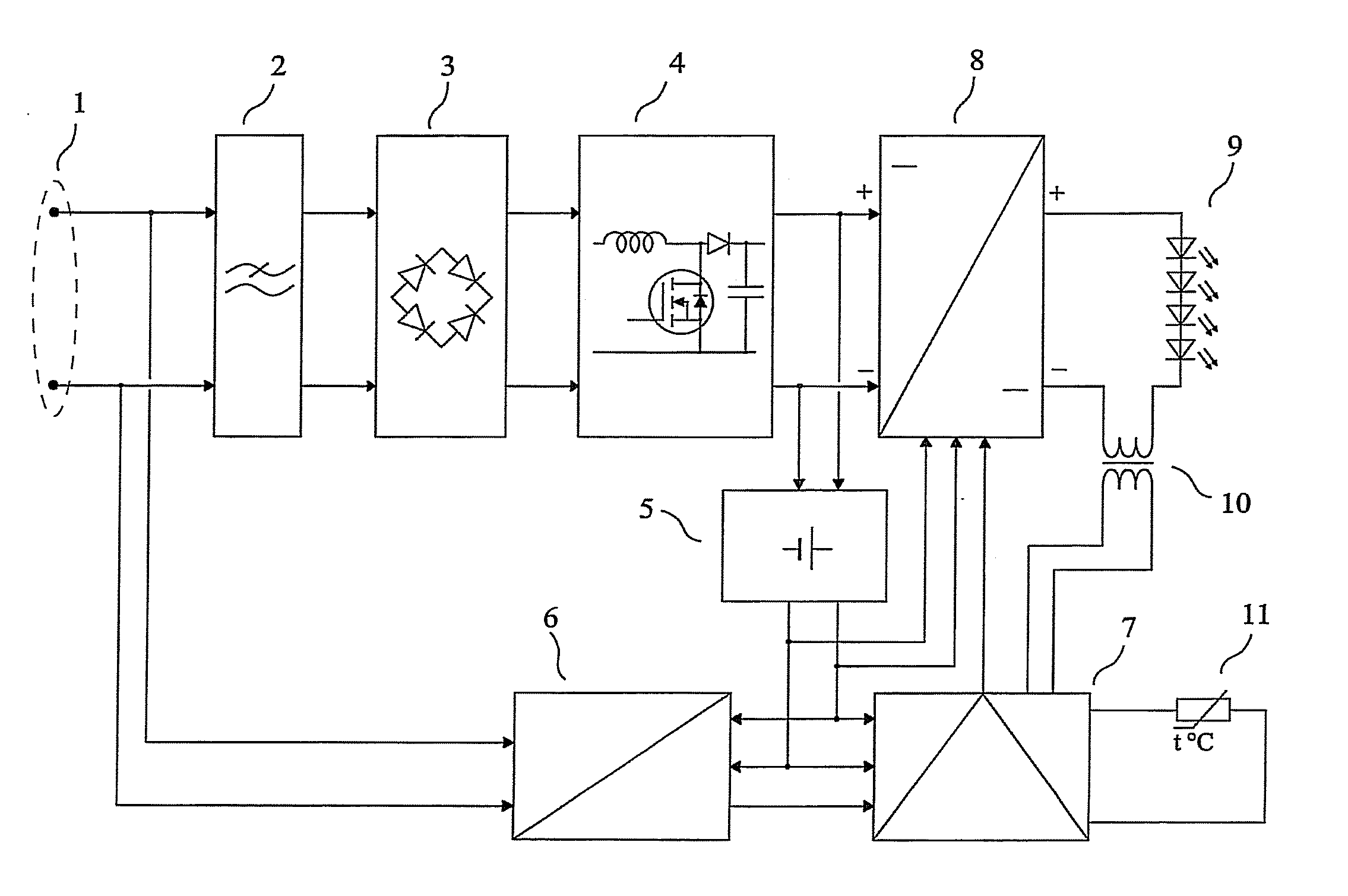
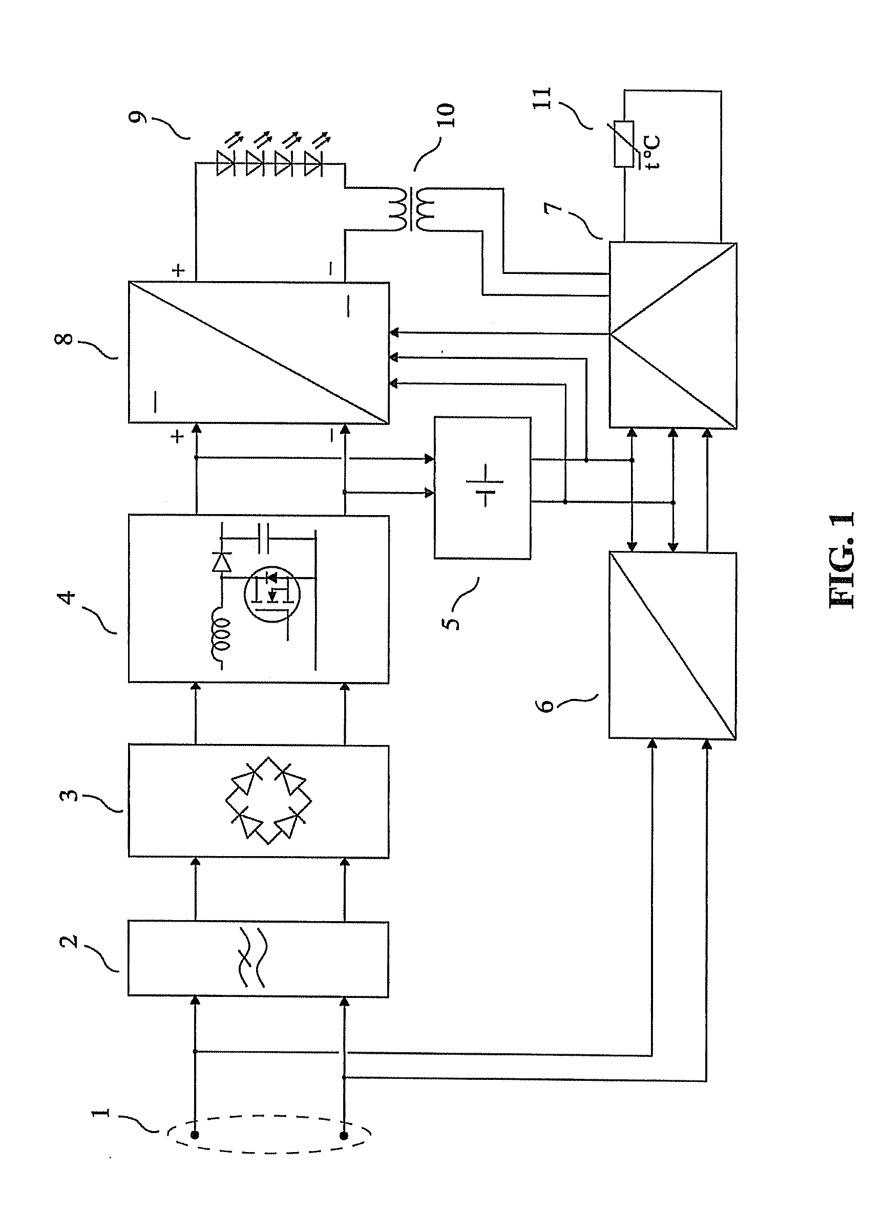
The invention relates to a transmitting device for transmission through space, using electromagnetic waves of the infrared and / or visible and / or ultraviolet bands produced by one or several diodes producing electroluminescent light.The device is connected by its input terminals (1) to an a.c. energy distribution system. A mains filter (2) reduces the conducted electromagnetic disturbances produced by the power circuits comprising a rectifier (3), a power-factor-correction circuit (4), an auxiliary power supply (5) and a DC-to-DC converter (8). The output of the DC-to-DC converter (8) is connected to several high power light-emitting diodes connected in series (9). A receiving set for transmission via power distribution lines (6) delivers demodulated signals applied to the control circuitry (7) which provides the current command of the DC-to-DC converter (8) and the modulated current applied to the light-emitting diodes (9) through the modulation transformer (10), as a function of the demodulated signals and of the temperature which is measured by a temperature sensor (11). The produced light is modulated as a function of the demodulated signals.

Description

FIELD OF THE INVENTION[0001]The invention relates to a transmitting device for transmission through space, using electromagnetic waves of the infrared and / or visible and / or ultraviolet bands produced by one or several diodes producing electroluminescent light.PRIOR ART[0002]In the following, the word “light” will designate an electromagnetic radiation which may comprise visible light and / or ultraviolet light. In the following, the wording “light-emitting diode” will designate any type of diodes producing electroluminescent light. This light-emitting diode may for instance be an infrared light-emitting diode, a high-power white light-emitting diode incorporating a phosphor, an organic light-emitting diode, etc.[0003]A transmitting device for free-space optical transmission, comprising one or more discharge lamps used as light source for transmission and a receiving set for transmission via power distribution lines, is described in the French patent application number 04 09939, entitl...

Claims


Application Information

Patent Timeline
IPC IPC(8): H04B10/00H01L33/00H04B10/114H04B10/116
CPCH04B10/116H04B10/1149H05B33/00H04B3/54H04B10/11
Inventor BROYDE, FREDERICCLAVELIER, EVELYNE
Owner ZXTALK ASSETAB
Learn More